• The move to the new server is done. There are some software and database maintenance updates in process. This has us passing the hat around to help out. We appreciate any donations. Seriously, even a dollar helps. The payment page may be found here - https://www.audiokarma.org/support.html

Sansui AU-777 Troubleshooting

Dvanamps

New Member
Hi folks,

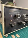
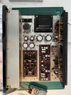
Im currently undergoing a full restore of a beloved Sansui AU-777 amplifier.

Have already been following threads by @Leestereo and @KeithD among others to gain better understanding.

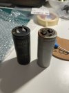
So far, I have redone the power supply caps and all is sounding good, I can already notice an improvement in bass response and perhaps some tighter mid range.

Before progressing further, however, i would like to resolve the initial issue which started this project off in the first place.

I am still experiencing a low level white noise when the amp is on, this is regardless of the input selection, source and volume level. Possibly some worn out transistors need replacing?

The second issue (possibly unrelated possibility not) is that the volume knob when set to zero, never fully reduces the output back to null. The amp will always play at very low level even when turned down fully.

Any help and advise on where best to start to tackle these issues would be very much appreciated.

Ive also considered changing/upgrading the power supply, plugs, leads etc, and perhaps reinstalling the original power on/off and protector bulbs as currently someone had installed a single led with resistor as a replacement. Not sure if that would help at all?

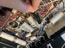
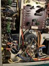
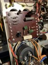
Anyway lots going on but see images of progress so far in the meantime.

Many thanks in advance for your help and guidance,

Dan
 

Attachments

  • IMG_6506.jpeg
    IMG_6506.jpeg
    142.4 KB · Views: 50
  • IMG_6512.jpeg
    IMG_6512.jpeg
    143.2 KB · Views: 51
  • IMG_6448.jpeg
    IMG_6448.jpeg
    125.8 KB · Views: 48
  • IMG_6445.jpeg
    IMG_6445.jpeg
    111 KB · Views: 47
  • IMG_6419.jpeg
    IMG_6419.jpeg
    73.8 KB · Views: 53
Register to hide this ad
What you are describing could be noisy transistors. One thing you can do to help isolate it is to remove the pre-out main-in jumpers in the back and then see if the noise is still there. If it is then the power amp section is the place to concentrate, if not then it is in the"preamp" section somewhere.

BTW it looks like you are doing a nice job.
 
"Ive also considered changing/upgrading the power supply, plugs, leads etc, and perhaps reinstalling the original power on/off and protector bulbs as currently someone had installed a single led with resistor as a replacement. Not sure if that would help at all?"

What does a single led mean? One at each location? or just one LED?

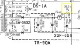
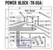
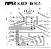
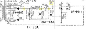
I would recommend putting the original protection bulb back in. The circuit design factors in the resistance of the bulb. You can check the voltage you are seeing with the LED in circuit. Look at point 9 on the TR-90A board.

777ps.jpg
 
Thanks for this information @mrk229

I starting investigating the above yesterday and as if by chance, before touching a thing, the amp made a loud pop when switching to speakers and is now emitting a rather loud hum on all programs from both chanels. It feels more like a grounding hum now although without any external input currently connected. This is the first time thats happened and not entirely sure why.

Secondly, I did check point 9 on the TR-90 block and it was reading 1.37v DC which seems wrong? Also after having the unit on for a few minutes i noticed R906 getting extremely hot and notice a burning smell?

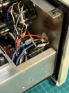
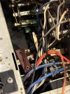
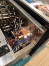
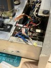
I also investigated the signal lamps and have attached images of how the single LED is wired up currently, seems odd to bypass the protector lamp altogether?

Any advice on how best to proceed would be welcomed at this point.
 

Attachments

  • IMG_6564.jpeg
    IMG_6564.jpeg
    183.1 KB · Views: 42
  • IMG_6563.jpeg
    IMG_6563.jpeg
    134.6 KB · Views: 41
  • IMG_6562.jpeg
    IMG_6562.jpeg
    147.2 KB · Views: 40
Thanks for this information @mrk229

I starting investigating the above yesterday and as if by chance, before touching a thing, the amp made a loud pop when switching to speakers and is now emitting a rather loud hum on all programs from both chanels. It feels more like a grounding hum now although without any external input currently connected. This is the first time thats happened and not entirely sure why.

Secondly, I did check point 9 on the TR-90 block and it was reading 1.37v DC which seems wrong? Also after having the unit on for a few minutes i noticed R906 getting extremely hot and notice a burning smell?
1.37 volts at B6 is telling me the amp is in protection mode,the question is why? Is it real or is it a failed component.
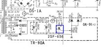
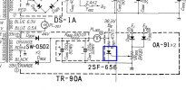
1. The 2SF-656 SCR when triggered on pulls B6 to ground through R907, lighting the lamp and reducing the voltage at B6.
2. The protection lamp has been bypassed (removed), and R906 without the lamp in series is dissipating almost all of the 44 volt supply, and around 4 watts of power. :eek:

Is the SCR being triggered on because of an amp fault or did it short out? Or is it something else in the amp circuit?

Lets check the SCR first.


777prot.jpg

Take your meter set for ohms and probe across the A (Anode) and the K (cathode), note the reading and then flip the polarity of the leads and note the reading again.
Flipping means swap the position of the meter leads, red where black was and vice versa. We are looking to see if it is shorted.


777scr.jpg

I also investigated the signal lamps and have attached images of how the single LED is wired up currently, seems odd to bypass the protector lamp altogether?

Any advice on how best to proceed would be welcomed at this point.


Wow whoever worked on that before did you no favors. It looks like something has burnt up in that area. The original sockets are gone making your work much harder.
That power on LED looks like a short waiting to happen. I see open solder joints all around it.

You don't happen to have the original protection bulb do you? If not we will need to source one at some point.

And last but not least are you using a Dim Bulb tester?
 
I looked at your pictures again, I thought the protection lamp had been bypassed with a butt connector, I'm not so sure now. It may be shrink tube?

If it is shrink tube is there something inside it besides the wires?
 
Thanks @mrk229 for all for your input so far. I have followed your instructions with the following results.

SCR901 measures at 0.0ohms in both positions. It reads at 0.744 between anode and gate. Not sure if thats relevant.

I have ordered new lamps and they should be arriving soon. The closest i could find to replace the 25V 90mA protector lamp is 25V 100mA but main indicator is to spec.

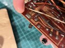
Also, as predicted, after removing the shrink tube for current protector connection I uncovered something interesting.

Lastly, i had a look at how the lamps are currently setup in my 777 tuner and notice the bulbs are covered with black rubber. Does anyone know where to source something like this or otherwise a good alternative method for shielding the light?

Have attached some pictures below for reference in the meantime and will update further once bulbs have been replaced.

Thanks again,
 

Attachments

  • IMG_6663.jpeg
    IMG_6663.jpeg
    130.5 KB · Views: 29
  • IMG_6662.jpeg
    IMG_6662.jpeg
    130 KB · Views: 29
  • IMG_6674.jpeg
    IMG_6674.jpeg
    136.2 KB · Views: 28
  • IMG_6676.jpeg
    IMG_6676.jpeg
    101 KB · Views: 28
  • IMG_6665.jpeg
    IMG_6665.jpeg
    100.8 KB · Views: 31
It looks like the SCR is shorted. Pull it out and check it again once it is off the board. It seems like the person who messed with the lamps tried to at least emulate the resistance of the bulb. Guess they did not know or care that the resistance of a filament lamp goes up when it is lit. I can't really see the colors of that resistor, out of curiosity what value is it?

I have seen bulbs that had black paint applied to stop stray light. perhaps a careful coating of black silicone in the proper part of the bulb would work?
 
Last edited:
Quick update on how things are progressing.

I have so far managed to source the correct lamps and restored things as originally intended. Also managed to find a supplier for high temp silicon end caps (normally used for sandblasting applications) which should work well as bulb covers.

After firing up the amp however, same problem still persists, the amp is flatlining, no output to speakers besides a constant grounding tone. Oddly, the newly installed protector bulb does not light up either, strange. Could it be that the amp is not in protection mode but is shorting due to a faulty component instead?

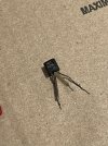
I pulled the SCR901 and tested it again, still reading 0.0 ohms in all directions, is it safe to say the component is now bust? If so, any good re-placements for the existing NEC F656 and to what spec? I’m going to hold off on other replacements until this issue is identified for the time being.

If there are any other tests worth running or other places I should be looking in the meantime, I’m all ears. Hopefully this feed will prove useful for other 777 repairs in future.

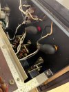
Progress pictures attached

Cheers
 

Attachments

  • IMG_6729.jpeg
    IMG_6729.jpeg
    110.3 KB · Views: 19
  • IMG_6731.jpeg
    IMG_6731.jpeg
    172.3 KB · Views: 21
  • IMG_6730.jpeg
    IMG_6730.jpeg
    111.5 KB · Views: 20
  • IMG_6728.jpeg
    IMG_6728.jpeg
    131.9 KB · Views: 18
  • IMG_6727.jpeg
    IMG_6727.jpeg
    114.3 KB · Views: 20
Quick update on how things are progressing.

I have so far managed to source the correct lamps and restored things as originally intended. Also managed to find a supplier for high temp silicon end caps (normally used for sandblasting applications) which should work well as bulb covers.

After firing up the amp however, same problem still persists, the amp is flatlining, no output to speakers besides a constant grounding tone. Oddly, the newly installed protector bulb does not light up either, strange. Could it be that the amp is not in protection mode but is shorting due to a faulty component instead?

I pulled the SCR901 and tested it again, still reading 0.0 ohms in all directions, is it safe to say the component is now bust? If so, any good re-placements for the existing NEC F656 and to what spec? I’m going to hold off on other replacements until this issue is identified for the time being.

If there are any other tests worth running or other places I should be looking in the meantime, I’m all ears. Hopefully this feed will prove useful for other 777 repairs in future.

Progress pictures attached

Cheers
During the testing was the SCR in or out of the PC board?

777prot.jpg
While writing this I just noticed that it looks like your sockets are not isolated from the mounting tab? Meaning one side of the socket is grounded through the mounting screw. :yikes: Not a giant deal for the power lamp but it should be fixed.

It is a big deal for the protection circuit. Since the lamp is not lit the wire at the shell of the socket is probably coming from R906 and would be shorting the power to ground .
Again :yikes:.


For now float the socket from the chasis for testing. Check the voltage at B6 on the PC board.

Assuming the SCR is shorted it should not be on the PC board for the test.
 
Sub for the 2SF565: Pinout may not be the same.

 
After firing up the amp however, same problem still persists, the amp is flatlining, no output to speakers besides a constant grounding tone. Oddly, the newly installed protector bulb does not light up either, strange. Could it be that the amp is not in protection mode but is shorting due to a faulty component instead?
The AU-777 has no protection circuit, so I'm unclear what you mean by "protector bulb."

Assume you have the service manual. The hum on all sources is a fault mentioned in the SM on page 7:

Screenshot 2024-10-19 at 9.53.59 PM.png
 
The AU-777 has no protection circuit, so I'm unclear what you mean by "protector bulb."

Assume you have the service manual. The hum on all sources is a fault mentioned in the SM on page 7:

View attachment 3324735
Hi Keith,

it looks like there is a protector circuit in the 777, see the post of the power supply section of the schematic a couple of posts up. PL002 is the protector lamp, and it is lit if the SCR 2SF-656 Is triggered. The SCR is triggered from the voltage across lower emitter resistors of each channel. If the current is exceeded, the SCR is triggered, and the voltage at B6 is effectively grounded. B6 supplies the input stage of the power amps, so if the protector SCR is triggered it disables both power amps.

Cheers
John
 
Hi Keith,

it looks like there is a protector circuit in the 777, see the post of the power supply section of the schematic a couple of posts up. PL002 is the protector lamp, and it is lit if the SCR 2SF-656 Is triggered. The SCR is triggered from the voltage across lower emitter resistors of each channel. If the current is exceeded, the SCR is triggered, and the voltage at B6 is effectively grounded. B6 supplies the input stage of the power amps, so if the protector SCR is triggered it disables both power amps.

Cheers
John
Hi John,

Thanks for the correction on that. Since the 777 does not have a separate protection circuit board, I never realized that part of the PS serves as protection.

Keith
 
I’m getting the following voltage readings on the TR-90A power block board with SCR removed.

A1 - 0.13
A2 - 0.13
A3 - 45.86

A10 - 19.54

B4 - 37.43
B5 - 0.03
B6 - 0.03

B9 - 36.3

Have placed an order for a few replacement resistors in the meantime. I also have components for a full recap but would like to understand the problem before replacing further. Cheers
 
I’m getting the following voltage readings on the TR-90A power block board with SCR removed.

A1 - 0.13
A2 - 0.13
A3 - 45.86

A10 - 19.54

B4 - 37.43
B5 - 0.03
B6 - 0.03

B9 - 36.3

Have placed an order for a few replacement resistors in the meantime. I also have components for a full recap but would like to understand the problem before replacing further. Cheers
Do you have a way to test that transistor to see if its shorted? I can open my 777 up and make some measurements if it'd be helpful.
 
I’m getting the following voltage readings on the TR-90A power block board with SCR removed.

A1 - 0.13
A2 - 0.13
A3 - 45.86

A10 - 19.54

B4 - 37.43
B5 - 0.03
B6 - 0.03

B9 - 36.3

Have placed an order for a few replacement resistors in the meantime. I also have components for a full recap but would like to understand the problem before replacing further. Cheers
I think you are missing an important thing here. A1 and A2 will be AC voltages, I bet you were looking for DC?
The A3 voltage tells me the AC voltages are present or you would have no DC after the diodes.

C6 is off the board and the plus side is connected to pin A3. 45vdc

The voltage also goes through R906 and off board to at pin B4, which you have as 37.43 which is good.

Now it could go a few different ways from pin B4.
A: Wire from pin B4 to the + side of C7, and a second wire going to one side of the protection lamp socket. Did you isolate the socket from the chassis? The socket terminal should also have the same voltage as pin B4.

B: Wire from pin B4 to the + side of C7 and then another wire on the + side of C7 to the protection lamp socket. Again should have same voltage at the socket as pin B4.

Can you confirm this so far? ( I think your voltages confirm it but want to be sure since somebody messed with things)

The second terminal of the protection lamp socket will probably have its wire coming back to B9. ( again I think your voltages confirm this)

Please confirm and or give me the connections you have in your chassis.

After this the plot thickens, because we have a bunch more components on the TR-90A board than the small schematic section shows.

R901, R902, R903, R904, R905, R908, C901, and C902 are not on the small schematic section below.

I found most of them sprinkled about in the larger schematic. We can trace them through after you let me know what is where on your amp.

777board.jpg777pscheck.jpg
 
I was deep diving into the full schematic last night and found all of the parts and connection points that are not on the "simplified" schematic section we have been looking at.
I doubt the person who "fixed" the lamps hacked up the power distribution. Based on what I can see in the pictures you posted earlier it looks like the wiring from/to the TR-90A board is untouched, but let me know what you find.

As it turns out there are two voltages from the TR-90A to the power amp boards. 36.3 volts at B9 and 19.2 volts at A10.

The extra components on the TR-90A I mentioned in the previous post are for the center channel output and have nothing to do with power or protection.

I think we are zeroing in on the problem.
 
Do you have a way to test that transistor to see if its shorted? I can open my 777 up and make some measurements if it'd be helpful.
I just checked with my multimeter with the thyristor removed from the board and got the following readings.

0.703v in diode mode
4.9ohm

Seems okay after all?
 
Back
Top Bottom