• The move to the new server is done. There are some software and database maintenance updates in process. This has us passing the hat around to help out. We appreciate any donations. Seriously, even a dollar helps. The payment page may be found here - https://www.audiokarma.org/support.html

Sansui AU-777 Troubleshooting

Thanks, I have taken a few more readings and can confirm the following.

37.54v at B4 matches that at connection to PL002 lamp and to capacitor C7. Does this mean the problem is not to do with the power or protection circuit itself?

In my observations I also noticed some burning caps on TR-80A, C822 and C816, likely being caused by the hot R822 ceramic resistor. Also noticed a similar hot resistor previously on TR-90A board. Could this be a result of the new capacitors I have replaced in the power section? The amp did work and sound well after initial replacement.

Where to next?
 

Attachments

  • IMG_6735.jpeg
    IMG_6735.jpeg
    107.3 KB · Views: 8
Please go back to my post #18 and answer those questions for me.

Have you isolated the protection lamp socket from the chassis?

Does the B4 voltage going to the protection lamp come out of the other lamp terminal and show up at B6 and a little lower voltage at A10?

If the voltage does not go through the lamp and come back to B6 the amp won't work.

Leave the SCR out of the board for now. Does not need to be there for the amps to work.

Lets forget about the caps for now. Might be bad but not the root of the problem.

Does the side of that resistor facing the caps look blackened? do the caps have soot on them or is it shadows?
You can check the resistors in circuit.
 
Please go back to my post #18 and answer those questions for me.

Have you isolated the protection lamp socket from the chassis?

Does the B4 voltage going to the protection lamp come out of the other lamp terminal and show up at B6 and a little lower voltage at A10?

If the voltage does not go through the lamp and come back to B6 the amp won't work.

Leave the SCR out of the board for now. Does not need to be there for the amps to work.

Lets forget about the caps for now. Might be bad but not the root of the problem.

Does the side of that resistor facing the caps look blackened? do the caps have soot on them or is it shadows?
You can check the resistors in circuit.

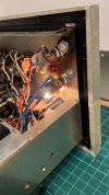
I have jimmy-rigged the lamps with a match stick for the time being so they are not attached to the chassis. See image attached.

B4 voltage does read correct going into the lamp, however, nothing at B6 0.1v only. A10 reads 19.45v.

Side of resistor not blackened. Caps do have soot however. I’ve checked resistors and they read fine. Also checked resistors on TR-90 with the following results.

R901 - 2.2 fall
R902 - 2.2 fall
R903 - 0.1 ohm ?
R904 - 10.1
R905 - 10.4
R906 - 355.2
R907 - 4.7
R908 - 6kohm

Have I missed something? Perhaps protector lamp wired up in correctly?
 

Attachments

  • IMG_6736.jpeg
    IMG_6736.jpeg
    90.2 KB · Views: 10
The protector lamp does not look like it is screwed in far enough. Ohm check from the center connection of the socket to the shell.
If you get an open, then ohm check the bulb and if it is good then the center of the socket is not making contact with the bulb for some reason.

Ignore R901 through 905, as I said they are part of the center channel output and have nothing to do with the power or protect circuits.

R907 is good and R908 is good. You need to get voltage from B4 through the lamp and back to B9

Not sure why you would have voltage at A10 though. Is SCR 901 installed on the PC board?
 
Ohm checked both lamp and socket, all reads fine. SCR 901 is still removed yes.

B4 - 37.4v
B9 - 36.4v

Do we have lift off?
 
Ohm checked both lamp and socket, all reads fine. SCR 901 is still removed yes.

B4 - 37.4v
B9 - 36.4v

Do we have lift off?
Something changed in the lamp circuit as you now have voltage at B9, which was not there before.

Go ahead and see if it is working now. If not we need to confirm the voltages are getting to the amp boards.
 
Something changed in the lamp circuit as you now have voltage at B9, which was not there before.

Go ahead and see if it is working now. If not we need to confirm the voltages are getting to the amp boards.

The amp is now working and sounding good! It may well have been that the protector lamp was loose as you suggested, a common problem I know. I have now reattached the lamps with shielding. Will also reinstate the SCR later and see if the problems reoccurs again.

I also have a theory that the main power cap might be a touch tall and could possibly be coming in contact with the under carriage plate when it’s attached.

Will continue with the restore from here and keep you posted on how things progress. Glad we got the original bulbs replaced and things working as normal again, for now.

Best
 

Attachments

  • DD924B41-A152-4350-A74A-518DF50FB302.jpeg
    DD924B41-A152-4350-A74A-518DF50FB302.jpeg
    87.7 KB · Views: 16
  • 28AD7BC7-3CD8-4E2B-8A9A-962CFF6DD7E5.jpeg
    28AD7BC7-3CD8-4E2B-8A9A-962CFF6DD7E5.jpeg
    88.3 KB · Views: 16
Hey that works to Isolate the lamp socket, I was going to suggest a plastic screw and some type of insulator.

Sansui almost always put what looks like a band of paint around the protection lamp socket and the bulb where they met to keep the lamp from unscrewing.

Glad it is working. If it were mine I would not put the old SCR back, I would get a new one when I ordered some other parts.

Definitely do not want the cap touching the bottom plate. :yikes: If any doubt put a few layers of electrical tape on the plate where the cap is.

Way to persevere, I am glad it is working again, and the crappy repairs have been removed.

:rockon:
 
Last edited:
What you are describing could be noisy transistors. One thing you can do to help isolate it is to remove the pre-out main-in jumpers in the back and then see if the noise is still there. If it is then the power amp section is the place to concentrate, if not then it is in the"preamp" section somewhere.

BTW it looks like you are doing a nice job.
Hi @mrk229,

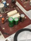
Quick progress update. I have now finished recap of the main amplifier driver (TR-80A) and so far so good.

That said, i am still getting a rather loud white noise (airy sound) coming through the speakers when nothings playing, as before. This increases substantially when the volume is turned up. I have tried biasing and regulating voltage across channels without much success. Turning the bias down on each channel does reduce disturbance slightly but intern produces a distorted sound.

Regarding your previous advise, where can one locate the pre-out main in jumpers exactly? Id now like to get to the bottom of this potential noisy transistor issue and see if the effects can be resolved or at very least reduced.

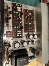
Any pointers would be much appreciated. Have attached pictures of progress so far for reference.
 

Attachments

  • IMG_6842.jpeg
    IMG_6842.jpeg
    147.9 KB · Views: 15
  • IMG_6750.jpeg
    IMG_6750.jpeg
    104.7 KB · Views: 14
Regarding your previous advise, where can one locate the pre-out main in jumpers exactly? Id now like to get to the bottom of this potential noisy transistor issue and see if the effects can be resolved or at very least reduced.

Any pointers would be much appreciated. Have attached pictures of progress so far for reference.
Jumpers are on the back next to the tape RCA jacks.

I see from your picture you have not changed the trimmers. I highly recommend doing that for better control when setting bias and DC balance.
 
Jumpers are on the back next to the tape RCA jacks.

I see from your picture you have not changed the trimmers. I highly recommend doing that for better control when setting bias and DC balance.
Great thanks, I removed the jumpers and the airy noise still persists, although it does not increase when volume is applied which I guess makes sense.

Based on these findings i will first tackle the power amp transistors and report back with results.

Also, I have acquired the replacement trimmers but have not gotten round to replacing them yet, thats next on the list.

Cheers
 
Great thanks, I removed the jumpers and the airy noise still persists, although it does not increase when volume is applied which I guess makes sense.

Based on these findings i will first tackle the power amp transistors and report back with results.

Also, I have acquired the replacement trimmers but have not gotten round to replacing them yet, thats next on the list.

Cheers
I didn't need to change any transistors on my 777, but would be interested in what you replace and use for replacements.
 
I didn't need to change any transistors on my 777, but would be interested in what you replace and use for replacements.

Here are the proposed replacements. It's quite tricky as 2SC650 and 2SC281 are quite similar in terms of specs. All are TO-18 metal casings as per original.

2SC650 - BC109C - BJT NPN Trans 30Vcbo 25Vceo 5.0Vebo 600mW 150 MHz
2SC281 - BC108B - BJT NPN Trans 30Vcbo 25Vceo 5.0Vebo 600mW 150 MHz
2SC283 - BC107A - BJT NPN Trans 50Vcbo 45Vceo 6.0Vebo 600mW 150 MHz

Option to any suggestions or comments of course.
 
Here are the proposed replacements. It's quite tricky as 2SC650 and 2SC281 are quite similar in terms of specs. All are TO-18 metal casings as per original.

2SC650 - BC109C - BJT NPN Trans 30Vcbo 25Vceo 5.0Vebo 600mW 150 MHz
2SC281 - BC108B - BJT NPN Trans 30Vcbo 25Vceo 5.0Vebo 600mW 150 MHz
2SC283 - BC107A - BJT NPN Trans 50Vcbo 45Vceo 6.0Vebo 600mW 150 MHz

Option to any suggestions or comments of course.
Thanks for the info. I don't have any comment or suggestion. From the comments I'd read in various threads about the 777 a couple of years back, opinions seemed to be that almost none of the transistors in the 777 had satisfactory equivalents today. So I think many that work on these end up not replacing any transistors. Fortunately on my 777 I was not having any issues when I did the re-cap and changed the trimmers, so I did not feel a need to consider changing any transistors. I'll be interested to read your experience with replacing transistors. Keep us posted.
 
Hi group,

So its approaching two years now since i finished the recap and restore of the Sansui AU777 amp and it has since been performing well and producing a great sound i might add.

Until last weekend, when the previously mentioned formidable protection lamp has turned on!

I now have the amp disconnected and on the bench for closer examination.

The red protector light turns on aprox 30 seconds to a minute after turning the amp on.

I am then unable the adjust any bias or output voltage via the VRs.

Where should i be testing next? Any pointers on where to look first? Could this be the SCR finally packing in?

Any help or advise would be greatly appreciated at this stage.

Thanks
 
Hi group,

So its approaching two years now since i finished the recap and restore of the Sansui AU777 amp and it has since been performing well and producing a great sound i might add.

Until last weekend, when the previously mentioned formidable protection lamp has turned on!

I now have the amp disconnected and on the bench for closer examination.

The red protector light turns on aprox 30 seconds to a minute after turning the amp on.

I am then unable the adjust any bias or output voltage via the VRs.

Where should i be testing next? Any pointers on where to look first? Could this be the SCR finally packing in?

Any help or advise would be greatly appreciated at this stage.

Thanks
Did you change out the old trimmers?
 
Back
Top Bottom