• The move to the new server is done. There are some software and database maintenance updates in process. This has us passing the hat around to help out. We appreciate any donations. Seriously, even a dollar helps. The payment page may be found here - https://www.audiokarma.org/support.html

Sansui AU-919 Needs Love.

I am hoping that the installed 2SD424, 2SB554 output transistors will do for sacrificial duty, any reason not to use them?

i would love to use original transistors but finding a set of NMC1012, NMA1012 is not likely to happen. Most suitable T03 replacements are also no longer manufactured, hard to find and I don't want to risk ending up with fakes.

So from what i can gather 2SA2223A/2SC6145A T03P's may be my best shot. In the end I would rather adapt these to fit if they give the best currently available compatibility. Colour me shocked to find that these are no longer produced and we are now in while stocks last territory, again!

Anybody have thoughts on the 2SA2223A/2SC6145A path and/or do i have better options?.
Hi Alex ,
Congratulations for the AU-919 . I have restored an AU-907 limited, the sound is impressive but not my “cup of tea” 100%.
My OP wasn’t blown but I was considering the 2SA1294/2SC3263 as a good substitute, you might want to take a look at those .

Good luck with your project, I’m sure you can tackle this with no problems ;)
 
Hi Alex ,
Congratulations for the AU-919 . I have restored an AU-907 limited, the sound is impressive but not my “cup of tea” 100%.

I'm looking forward to hearing it for the first time. I'm mostly using my AU-717 at the moment and really like the sound. We will see which one suits my tastes more, I will be happy whichever way it goes.

My OP wasn’t blown but I was considering the 2SA1294/2SC3263 as a good substitute, you might want to take a look at those .

From what I can gather they would be fine but maybe there are better options, I will keep them in mind. Choices get more limited every year by the looks of things.
 
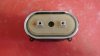
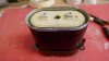
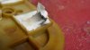
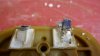
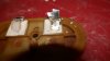
Decided to investigate the capacitor further. Cut the leads and again tried to take a measurement, to my surprise both capacitors inside are functioning! I could have repaired it!!!!!!!!

The problem lies in the connection between the capacitors and the terminal on top.

So for anyone with a bad oval capacitor it could be repairable, do yourself a favour and take a look inside, nothing to loose really.
I already ordered replacements but would have considered keeping the originals if I would have known. Still I will be happy to have new main caps.

This really surprised me.
P1040067.JPG


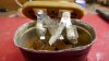
Looks like this joint failed. Not sure why. Power surge?
P1040064.JPG

P1040065.JPG
 
Took some of the silicon off the connection. The point of failure can be seen in the photo.
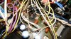
On F-2845 D02 burnt out with I believe damage to the traces underneath. A lot of heat was generated in a small area.

P1040069.JPG

P1040070.JPG
 
I was just surprised that it showed any life at all.
New caps are in the post.

Yes, I understood, and is a surprise. It's the ESR that gives away it state. If you would only measure the capacitance you could be fooled in thinking it was still ok. Was this one on the same side as the replaced rectifier? If so, they probably went out in the same event.
 
Was this one on the same side as the replaced rectifier? If so, they probably went out in the same event.

Yes, this is C03. D02 is on top of it. D02 is burnt out quite nicely. The underside of F-2845 shows an attempted repair but the heat damage there is still visible.
I will remove F-2845 and use some of the time until the parts arrive to desolder and test every component on it to try to get a handle on how localised the damage is.

D02
P1030965.JPG


Underside with attempted repair by previous owner.
P1040080.JPG
 
Well I took out F-2845 to take a better look at it, a replacement will be going inside anyway.

Tested al the electrolytics they all read close to their specified values with esr's mostly in the low 0.20's.
All the resistors test fine.
The diodes test as diodes. Except D01 witch is nicely burned. Previously I kept calling it D02 as I located it in the service manual but of course I was looking at the foil side.

The two yellow wires close to D01 look like they also burned and have been reconnected by someone.
So far the damage I have seen is localised to D01, C703 and the two yellow wires.

New capacitors inside the oval ones and the replacement F-2845 should take care of the problems I have found so far.


The connectors have obviously been repaired.
P1040085.JPG
 
Decided to investigate the capacitor further. Cut the leads and again tried to take a measurement, to my surprise both capacitors inside are functioning! I could have repaired it!!!!!!!!

The problem lies in the connection between the capacitors and the terminal on top.

So for anyone with a bad oval capacitor it could be repairable, do yourself a favour and take a look inside, nothing to loose really.
I already ordered replacements but would have considered keeping the originals if I would have known. Still I will be happy to have new main caps.

This really surprised me.
View attachment 2778403


Looks like this joint failed. Not sure why. Power surge?
View attachment 2778404

View attachment 2778405

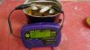
Actually over 1ohm ESR disqualifies them for further use, at least if this meter show correct values
 
Actually over 1ohm ESR disqualifies them for further use, at least if this meter show correct values

Yes it has to be replaced anyway. But I could maybe have used it for testing the amp before buying eight replacement caps.
In my case it makes no difference, someone else may have useable caps inside and a repair is possible.
 
For correct measurment of resistance under 1ohm there should be used 4-wire methood.

Such testers apply wires resistance to the measurment value.
Lets say shorted wires have 0.6ohm
1.1-0.6=estimated real esr

Interesting, thank you.
 
For correct measurment of resistance under 1ohm there should be used 4-wire methood.

Such testers apply wires resistance to the measurment value.
Lets say shorted wires have 0.6ohm
1.1-0.6=estimated real esr

Although your statement is correct luckily we mortals can use this simple ESR meter to give us an approximation.
I use one too, and because you can calibrate it to take out the wire resistance, you can measure low values.
Example from my AU-D907:

upload_2023-1-28_18-30-43.png

It even mentions the 4 wire method to be more precise in the manual.
It also gives the opportunity to calibrate it to values measured with an LCR meter so it is more accurate.
I am still saving for a good LCR meter, just have to stop buying amplifiers ;)!
 
Back
Top Bottom