• The move to the new server is done. There are some software and database maintenance updates in process. This has us passing the hat around to help out. We appreciate any donations. Seriously, even a dollar helps. The payment page may be found here - https://www.audiokarma.org/support.html

Sansui AU-919 Needs Love.

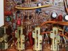
If they are the B536/D381, they are the correct replacements. Same transistors as the B537/D382 which where from factory made for horizontal installation with base and emitter leads bent and collector lead cut.

Thanks for the info, I will take a look at them.
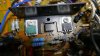
 
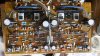
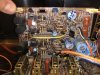
Just a suggestion: you should mount your Black Flag replacements lower in the board - all the way down so the horizontal kinks in the leads rest on the board. Lead Length = Inductance = Degraded capacitance effect.

My apologies if this is how you found the board - I see glue remaining, I am pretty sure you know that you have to remove that. ;)
 
Last edited:
Just a suggestion: you should mount your Black Flag replacements lower in the board - all the way down so the horizontal kinks in the leads rest on the board. Lead Length = Inductance = Degraded capacitance effect.

My apologies if this is how you found the board - I see glue remaining, I am pretty sure you know that you have to remove that. ;)

I did this on purpose, I still need to recap am just doing the black flags for now and see if I can get her running. The caps with the insanely long leads have glue under them which will be removed later, just didn't want to trim them yet.

I am happy to have you keep your eye on my antics, could save me from all kinds of fun and games.
 
I have 2 each of MJE15030/MJE15031, extras from my 717 when i needed to replace one channel of unidentified transistors. If I get really lucky The originals from the good channel of the 717 haven't found their way into the garbage, that would be just the ticket.
 
Last edited:
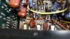
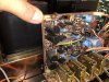
The replaced resistors (x2) in the left side of the picture are Metal Film types, the originals were Metal Oxide, the Metal Films are preferable and much better than the originals. They will slightly affect the sound (in a good way IMO), but whatever happens, they should be the same in both channels for this reason. You should include attention to these in your re-cap follow up. ;)
 
They will slightly affect the sound (in a good way IMO), but whatever happens, they should be the same in both channels for this reason. You should include attention to these in your re-cap follow up. ;)

This is why I try to post pictures, to catch things I may have missed.

I have of course noticed them, and will be replacing them in both channels once I get into the recap.
The service manual shows that I will need 560Ohm 1/3 watt, and 47Ohm 1/2 watt.
I will have to put them on my shopping list.
Any preferred replacements?
 
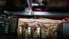
I'm having a clearance issue with F-2841, although I took plenty of photos none from before removal give me a clear view of jumper wire jp02.
I tried putting the wire behind the connectors between boards but the wire prevents F-2841 seating down low enough.
The cable itself wants to go a different route and run between the connectors and then there is clearance, just. I just looks wrong to me and I cannot be sure how it was originally.

The wire is top left on F-2841.
P1040200.JPG

This is how the wire wants to route, between the connectors.
P1040199.JPG

I'm guessing anyone who has removed this board came across a similar issue. Not a big deal, but I find the positioning strange.
 
I'm having a clearance issue with F-2841, although I took plenty of photos none from before removal give me a clear view of jumper wire jp02.
I tried putting the wire behind the connectors between boards but the wire prevents F-2841 seating down low enough.
The cable itself wants to go a different route and run between the connectors and then there is clearance, just. I just looks wrong to me and I cannot be sure how it was originally...

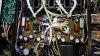
I don't have a picture of the F-2846 board clearly showing the wire in question, but from the picture below the wire does appear to be in front of the connector.
F-2846 wire.jpg
 
I think ( I’m not 100% sure ) that the AU-907 Limited is sharing the same board.
Here is all the photos I have , hope it helps !
 

Attachments

  • 005B3382-2ED0-4DA4-8E35-E01CD4F88EC9.jpeg
    005B3382-2ED0-4DA4-8E35-E01CD4F88EC9.jpeg
    178.2 KB · Views: 17
  • B46AF465-02C5-4392-A0E4-ADC211C21150.jpeg
    B46AF465-02C5-4392-A0E4-ADC211C21150.jpeg
    149.9 KB · Views: 18
  • 646C7232-8A79-478C-BC56-1C33B0155C62.jpeg
    646C7232-8A79-478C-BC56-1C33B0155C62.jpeg
    166.8 KB · Views: 16
  • 603A5D25-52D8-47C8-A2AC-1DBE72282D17.jpeg
    603A5D25-52D8-47C8-A2AC-1DBE72282D17.jpeg
    141.8 KB · Views: 18
  • FE1FF771-524B-4BA5-AFB7-9149CE4DF090.jpeg
    FE1FF771-524B-4BA5-AFB7-9149CE4DF090.jpeg
    137.5 KB · Views: 17
I'm guessing anyone who has removed this board came across a similar issue. Not a big deal, but I find the positioning strange.
I remember having this issue, (if we are talking about the orange wire), and I think it is possible that the wire was underneath the connector pins originally. But I can remember thinking that if the wire (routed under the pins), rests on the pins or is in any way pressed against the pins, that the heat from re-soldering the connectors might melt through the wire insulation. I can't remember now if I routed the cable under the connectors (making sure it wasn't pinched), or if I routed it outside the connector pins - I remember it was a little tight running outside the pins, I may have lifted the soldered crimps (on the orange wire), a little to ease that. (sorry if that's a bit unclear, I've only done four of them :rolleyes: ).
 
Last edited:
Thanks for all your replies and photos.
I get the best clearance running the wire between the first and second pins, I put a little clear shrink on the first and second pins where they run close to the metal connection of the wire to the board, just for safety

I am ready to put the amplifier back together but am taking my time, somehow I'm not in a rush to try to power it up.
I think I'm afraid that it could have a dead transformer, and I don't really want to know.
 
Last edited:
Back
Top Bottom