• The move to the new server is done. There are some software and database maintenance updates in process. This has us passing the hat around to help out. We appreciate any donations. Seriously, even a dollar helps. The payment page may be found here - https://www.audiokarma.org/support.html

Sansui AU 9500 Takes A Long Time to Turn On

TanMecEng

New Member
Hi,

I recently purchased a Sansui AU 9500 that had undergone a full service and partial recap. Upon receiving it, it took a longer than normal time for the speaker relay to switch on. Once the amp was warm and the relay had switched once, it worked perfectly and would switch at a normal time there after, until it cooled down, say a day later. Every additional time I play it, it does seem to take a longer and longer time. As of recently, I went to play the amp today and it took a very long time to turn on, 5-10 minutes, once it did turn on the sound was very off, sort of muffled and broken. This leads me to believe, unfortunately, that is more serious than just a speaker relay. Any help would be much appreciated, as I just got my beloved Sansui and haven't been able to listen to it much.

Regards,
Tanner
 
Register to hide this ad
OK, so what was done in the "partial recap?" Once the speaker relay clicks on, could you measure the DC coming out of the relevant speaker terminals and let us know? Yes there is something wrong. I would be interested to know what has been done. Any chance you could post a pic of the innards? Do you have a multimeter? Was it doing this as soon as you got it back from "service?"
 
undergone a full service and partial recap

If it only just received a partial recap, and is behaving erratically now, someone missed something, and is misdescribing the service it received. This should more accurately read 'partial service and partial recap'. :)
 
Hi,

To start off I would like to thank you guys for the replies. I am currently waiting for the seller to get back to me with a detailed list of what was done, but all I currently know is that the speaker relay was cleaned, 3 capacitors were replaced as well as all inputs were checked and controls cleaned. I will try to get pictures and the measurements as soon as possible, but I am going to be away from home for a day or two, so I may not be able to get them right away.

Yes it was doing it as soon as I received it from the seller, and yes partial service would be a more accurate title, I guess 'service' can be a very vague term.

I will hopefully get you all some more information soon, thank you again for the interest.

Tanner
 
It doesnt dound liek much has been molested with, in that case - however yea, check the cap polarity/values. Pics of the insides posted here woud also help.
 
Hi,

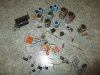
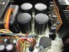
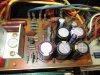
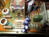
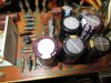
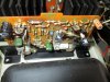
Sorry for the delayed response, but I was away for the weekend. I have uploaded some pictures that you all can have a look at, I do have more if needed just let me know. I also talked to the seller and he relayed to me some of what his tech had told him including:

"I replaced all the caps on the power supply/relay control circuit board, and most of the caps on the pre-amp board under the power supply board.
I'm wondering if anything happened in shipping."

Hopefully some of this can help. As for the tests you want me to perform, I'm generally quite capable with electronics, but if possible I would need a little more guidance.

Again, your help is much appreciated.

Regards,
Tanner
 

Attachments

  • IMG_3899 (800x600).jpg
    IMG_3899 (800x600).jpg
    271.3 KB · Views: 34
  • IMG_3919 (800x600).jpg
    IMG_3919 (800x600).jpg
    363 KB · Views: 34
  • IMG_3898 (800x600).jpg
    IMG_3898 (800x600).jpg
    301.7 KB · Views: 33
  • IMG_3900 (800x600).jpg
    IMG_3900 (800x600).jpg
    317.2 KB · Views: 32
  • IMG_3897 (800x600).jpg
    IMG_3897 (800x600).jpg
    291.8 KB · Views: 35
  • IMG_3838 (800x600).jpg
    IMG_3838 (800x600).jpg
    281 KB · Views: 35
  • IMG_3839 (800x600).jpg
    IMG_3839 (800x600).jpg
    261.1 KB · Views: 27
  • IMG_3833 (800x600).jpg
    IMG_3833 (800x600).jpg
    302.1 KB · Views: 32
  • IMG_3834 (800x600).jpg
    IMG_3834 (800x600).jpg
    297.6 KB · Views: 34
  • IMG_3829 (800x600).jpg
    IMG_3829 (800x600).jpg
    220.8 KB · Views: 31
OK I take that back - he has removed a few things. Some questions:

* In the photo showing the amp from the top view (IMG 3900) - you have a spare slot - was this taken during the work and if so, was that PCB removed - or did YOU take the that photo and that means you have a missing PCB?

* Check the polarity of all the new capacitors - you shoud be able to easily spot these - check the positive and the negative against either the PCB markings or the overlay diagram in the service manual for that PCB. Ideally you want to also check the values of the new caps against what shoudl be in there (based on the service manual).

* He has removed 8 transistors. If the caps are all OK my last question would be - are the replacements adequate/correct and oriented around the right way?
 
On the Power Supply & Protector Block Board (F-2030), check TR901, TR902 and D908. Also note that C901 and C902 were replaced with what appears to be 2 pairs of capacitors in series rather than bi-polar types. And as mentioned above, check the DC offset. This post may be useful for comparison: F-2030-1 Restoration/Upgrade
 
Hi,

@slimecity: I believe the photo was just taken when the PCB was removed, as subsequent photos that I have show it as being there. As for the capacitors, I will try to check for correct orientation tonight, could that cause the type of issues I am experiencing now?

@Leestereo: Would you mind telling me how to correctly check the transistors and diode? If not I can just google it, but I trust it coming from you guys a little more. As for C901 and C902 I can see what you are talking about, will this affect anything? Also I am not sure how to check the DC offset, could you tell me how?

Sorry I am new to this stuff, so bare with me, any knowledge is much appreciated.

Tanner
 
WRT testing - you first want to be a bit confident with a soldering iron. Also get a meter. You want to safely remove those components (by not applying too much heat so that you damage the transistor/PCB and that you remove the solder properly - you may already know all this....) Leestereo has mentioned to test them and do a 6-way test on the transistors:


Diodes are far easier - they will conduct one way but not the other using a similar test as the transistor test procedure.

However before you do ANY of the above - yes test the DC offset. You will only be able to do this when the amplifier relay has switched the speakers on. Before turing on the amp, disconnect the speakers, select speaker "A" output (or any really) set your meter probes to mV and ram them up there (speaker + to + meter lead, and - to - meter lead) and tell us what you get.
 
Left the corrosive glue. Left some 2SA726 transistors. Yes, there were bi-polar caps in place of those four. Check the polarity of those.

I would suspect a weak relay driver transistor or high DC taking a bit to settle down.

Rob
 
So I measured the DC offset and it was bouncing between 8 and 9 mV, I would say that it probably averaged somewhere in the middle.

Again, the amp is taking longer and longer to turn on every time, and now when it does turn on the sound is way off (which was not originally the case). Not sure what this could mean?

What should I do first with the given information?

Thanks,
Tanner
 
Can you describe how the sound is "off" - in what way? In one or both channels?

Were you getting that mV reading in both or one channel? Are you sure the relay was engaged when you took those readings?

First thing to do - a quick visual check of the cap polarities as above. That will be the easiest. Also check the solder job for these under the PCB, do the solder joins look nice and clean, enough solder was used?

Report back when you have done the above bro.
 
Last edited:
Back
Top Bottom