• The move to the new server is done. There are some software and database maintenance updates in process. This has us passing the hat around to help out. We appreciate any donations. Seriously, even a dollar helps. The payment page may be found here - https://www.audiokarma.org/support.html

Sansui AU-999 recap and mod journey

DatGtrPlaR

Amuse your Muse
I had acquired this fine 999, which ultimately led me here to this forum for research, and it wasn’t before long that I became a Sansui fan. I always wanted to learn more about electronics and stereo repair, and it is quite serendipitous how this all happened. Not to long after that, I got a non-working 555a working great back to it’s stock form. I intend to do some mods to it later, but for now, it’s serving up tunes to enjoy as embark on starting some mods and a update/recap of components of this AU-999. I ordered some parts from mouser. Not everything was available. So I got most everything. I am a beginner at stereo repair, so advice, suggestions, criticisms, thoughts and prayers welcome. Kevzep was kind to give some advice to start. And thank you once again to the folks here that helped on my 555a.
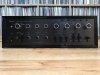
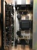
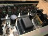
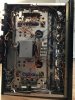
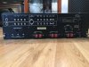
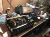
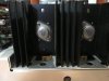
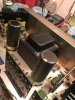
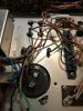
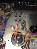
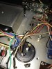
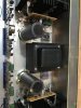
Here’s some pics.. this is a later model au999 w/out the subsonic circuit. It is all stock and is perfectly biased and aligned at the moment. Sounds pretty good so far…lacks a bit of bass, and the eq section isn’t as responsive as I would like it.. It is in great condition, except for the broken off power switch. It’s a nub at the moment, If anyone has a extra switch they want to hook me up with that would be wonderful!!….
 

Attachments

  • C588C6AD-C77B-4B31-8438-E5DE133A3B29.jpeg
    C588C6AD-C77B-4B31-8438-E5DE133A3B29.jpeg
    97.9 KB · Views: 189
  • 4A818DE0-F728-4F06-82CA-397E57E99894.jpeg
    4A818DE0-F728-4F06-82CA-397E57E99894.jpeg
    75.3 KB · Views: 176
  • 4ED3F560-C331-4010-95A1-B44C9EA929E3.jpeg
    4ED3F560-C331-4010-95A1-B44C9EA929E3.jpeg
    110.9 KB · Views: 187
  • 644EBA6F-587A-4B03-BFE9-A33F88DC3519.jpeg
    644EBA6F-587A-4B03-BFE9-A33F88DC3519.jpeg
    116.2 KB · Views: 189
  • 0C6BDE11-6121-4BF9-8E22-E961ECE2EDDD.jpeg
    0C6BDE11-6121-4BF9-8E22-E961ECE2EDDD.jpeg
    108.7 KB · Views: 189
  • FAD8C31A-7CC1-4DA3-B083-2537FF18D6F5.jpeg
    FAD8C31A-7CC1-4DA3-B083-2537FF18D6F5.jpeg
    138.7 KB · Views: 185
  • 21B01F11-2C30-44B1-9142-CB4C403CCF21.jpeg
    21B01F11-2C30-44B1-9142-CB4C403CCF21.jpeg
    103.6 KB · Views: 179
  • C62B2F48-C4BC-4FE8-A128-E18DC9964B0F.jpeg
    C62B2F48-C4BC-4FE8-A128-E18DC9964B0F.jpeg
    142.5 KB · Views: 189
Last edited:
Register to hide this ad
Lovely amp well done! There is a bass and pre amp mod I’m sure kevzep recommended to you which helps with bass - with a recap and particularly the main power supply filter capacitors replaced you may note a bass response improvement as well.
 
Congrats on your 999. Good news is that you need not suffer low bass output whatsoever - the 999 can absolutely huff and puff, but do need some mods including larger power supply and tad larger input caps (put something nice in here) . Once you get the amps resolution up - mostly done through a differential input balancing - you'll realize more bass, very noticeable with high res digital files. Avoid using the aux input for your best sources as the signal passes through a small diameter variable pot.

Lots of small tweaks here and there. Even a higher grade power cable (that is not like 9ft long) can bring out more dynamics.
 
Thats a very late production model July 1972!! There may be some things that do not need doing.
It might be good to pull the Head amp board and the tone boards out and have a look at what transistors are on those, because as far as I can see there are no "Flying Saucer" type transistors, and there may well be no 2SC458 in this amp either....
It's going to be a very straight forward job this one.
 
Congrats on your 999. Good news is that you need not suffer low bass output whatsoever - the 999 can absolutely huff and puff, but do need some mods including larger power supply and tad larger input caps (put something nice in here) . Once you get the amps resolution up - mostly done through a differential input balancing - you'll realize more bass, very noticeable with high res digital files. Avoid using the aux input for your best sources as the signal passes through a small diameter variable pot.

Lots of small tweaks here and there. Even a higher grade power cable (that is not like 9ft long) can bring out more dynamics.

Thanks for your reply! As I was researching here, I saw a couple parts list, one from you and ThaiBerra, and noticed that some of your capacitor values were a little higher, and in particular the C002&C003 being up to 12000uf 100v. I am a novice and got a couple Nichicon Super Through 6800uf 63v, because it seemed to be used more often. Can you educate me on this? Also, you mentioned the Aux input. I always have used the Aux as a go to input for my turntable>tube pre>Aux. Is there a way to make this input better? All this time I was missing out ..all inputs are not created equal. What are the best inputs? Where is this said pot located? I am currently using the Aux with the 555A at the moment. Does this amp have the same issue? Sorry to bombard you with the questions
Thanks in advance.
 
Thats a very late production model July 1972!! There may be some things that do not need doing.
It might be good to pull the Head amp board and the tone boards out and have a look at what transistors are on those, because as far as I can see there are no "Flying Saucer" type transistors, and there may well be no 2SC458 in this amp either....
It's going to be a very straight forward job this one.

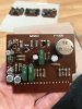
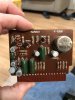
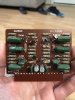
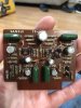
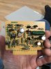
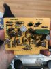
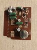
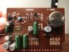
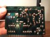
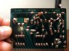
No flying saucers…here are some nice board pics..

also, what and where would be 2SC458?
 

Attachments

  • 56C1EAF2-B0CF-4983-9DB1-2233D4542DBA.jpeg
    56C1EAF2-B0CF-4983-9DB1-2233D4542DBA.jpeg
    85.2 KB · Views: 155
  • 8B72F1D3-26FA-4BA9-80BE-B647E1054976.jpeg
    8B72F1D3-26FA-4BA9-80BE-B647E1054976.jpeg
    94.1 KB · Views: 147
  • FD827560-03A6-41C4-8E6C-185F5BE744E5.jpeg
    FD827560-03A6-41C4-8E6C-185F5BE744E5.jpeg
    93.3 KB · Views: 142
  • 925BD792-A63A-4519-B724-EFBBC1FE13BA.jpeg
    925BD792-A63A-4519-B724-EFBBC1FE13BA.jpeg
    99.3 KB · Views: 141
  • 77D30BCB-9153-40E6-97C5-60751BE34E46.jpeg
    77D30BCB-9153-40E6-97C5-60751BE34E46.jpeg
    89.4 KB · Views: 138
  • 6CFA5245-8248-480C-91B2-07FA28CD26E4.jpeg
    6CFA5245-8248-480C-91B2-07FA28CD26E4.jpeg
    96.9 KB · Views: 133
  • AF49DA1C-977B-455E-B287-F067BB90C40E.jpeg
    AF49DA1C-977B-455E-B287-F067BB90C40E.jpeg
    68.7 KB · Views: 145
No flying saucers…here are some nice board pics..

also, what and where would be 2SC458?
If you look at the small signal transistors on the F1208/1209/1228-1 boards, see whats there, they don't look like C458's so you might not need to replace many at all...
 
Nothing wrong with the 6800 super through's, they fit really well too, and then you will be fine with leaving the original rectifier. The point is to add a bit more reserve than the stock 4400. Back in the day those were considered quite large and costly and "good enough."

The Aux input is normally like other inputs, less phono of course, however on the 999 they put a trim pot on the back allowing you to adjust the level of the incoming signal. Nothing wrong with that, but if you are going to connect a high-end DAC, then my preference would be to use the dedicated tuner or tape playback switches, for a cleaner signal path.

Most folks don't even know that there is a trim pot back there, so it has likely never been cleaned and could be as scratchy as any other 50 year old pot. So if you hook something up, give it a good clean/massage with deoxit first.
 
That is interesting, both phono inputs have trim pots too. Would it make any sense to just rewire/bypass the pots for all 3 inputs?
 
That is interesting, both phono inputs have trim pots too. Would it make any sense to just rewire/bypass the pots for all 3 inputs?
No, leave them, I have never experienced anything about the signal being degraded by the trim pots.....They doi generally need some attention with a touch of fader lube though, as they rarely are moved in their lives.
Personally I feel thats stretching it slightly to not use those inputs because of a degradation in singal, I used the Aux input on mine specifically so I could match the input level to the other sources....Its a very nice flexible function to have....
But each to their own......everyone has their own ideas and feelings on these things...
 
I am with Kevin - no need to remove or bypass aux trim pot - just know its there and clean + check it's position, if you are going to use it. Personally I skip it, unless I need it. It's a bit like some aux inputs on older cap couples models, where the signal is routed through the phono pcb. In those cases I prefer to use tape input which typically goes straight to the preamp. It's more principle than something audible.....although I do subscribe to the "many small creeks make a river" thinking, - so if you consistently throughout your rig can optimize small areas from inputs to speaker terminals, it begins to matter.
 
For something hot like a CD player, it would be useful. I always need to turn down when I flip from phono to CD.

I like tuners that have an output level adjustment, too. Switching sources can be more consistent
 
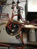
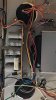
Well, I decided to put in the super through 63v capacitors in and the preamp mod to start. I wanted to check this out before I recap. Passed the dim bulb test. Then redid the alignment and bias. I went to hook up some tunes and it seems the output is very low.. I can crank the amp up to 10 and 10 sounds like it should be where 2 is. Very weak. I notice that when I turn the amp off and have music still going, it will suddenly get really loud then die out as the caps discharge. Any suggestions… here are some pics of my changes..does it look right? What to do?.. any suggestions?
 

Attachments

  • 25EB9DB5-12CA-4C1A-BB62-38BA1BB170F9.jpeg
    25EB9DB5-12CA-4C1A-BB62-38BA1BB170F9.jpeg
    110.2 KB · Views: 89
  • 962D3773-C363-4755-99E1-4D00D6E861C2.jpeg
    962D3773-C363-4755-99E1-4D00D6E861C2.jpeg
    122.6 KB · Views: 88
  • 5C253962-8038-4137-8F71-06DA22166BC4.jpeg
    5C253962-8038-4137-8F71-06DA22166BC4.jpeg
    146.3 KB · Views: 79
  • B682A8C8-8EA0-4273-AF27-882EE09EB506.jpeg
    B682A8C8-8EA0-4273-AF27-882EE09EB506.jpeg
    130.8 KB · Views: 76
  • D76A9D9C-FB4C-433C-B322-5BBFA3D16456.jpeg
    D76A9D9C-FB4C-433C-B322-5BBFA3D16456.jpeg
    161.4 KB · Views: 77
  • 4F1E0F2F-0D26-4D0F-9356-9C1E6655EC43.jpeg
    4F1E0F2F-0D26-4D0F-9356-9C1E6655EC43.jpeg
    123 KB · Views: 77
  • 191AC250-9596-4CA1-8E1E-0983A1C6FCFA.jpeg
    191AC250-9596-4CA1-8E1E-0983A1C6FCFA.jpeg
    98.4 KB · Views: 81
  • C0506B2F-C7D6-4F4D-9043-3F586FD17BCD.jpeg
    C0506B2F-C7D6-4F4D-9043-3F586FD17BCD.jpeg
    115.4 KB · Views: 79
Last edited:
What else have you done to it?
Have you plugged the pre-amp cards in the right way around?
Have you measured the main rail voltages from those Superthrough caps?
 
What else have you done to it?
Have you plugged the pre-amp cards in the right way around?
Have you measured the main rail voltages from those Superthrough caps?
The pre-amp cards can only go in one way because of the post on the side that ensures it won’t go in backwards. Measuring the rail voltage, do you do that by measuring the DC volts on the lugs of each Super Through cap withe the amp on? If yes then they read between 45-46DCv. Do they look like they are installed properly? Are the bias and output settings on the 1209 boards going to be same as the service manual or higher to accommodate the new main caps?
 
Last edited:
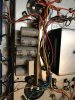
The pre-amp cards can only go in one way because of the post on the side that ensures it won’t go in backwards. Measuring the rail voltage, do you do that by measuring the DC volts on the lugs of each Super Through cap withe the amp on? If yes then they read between 45-46DCv. Do they look like they are installed properly? Are the bias and output settings on the 1209 boards going to be same as the service manual or higher to accommodate the new main caps?
Well, one should be a NEGATIVE DC voltage. The other POSITIVE DC voltage.
It is important these are the right way around too, did you note the wiring and what went where before you took the old caps. I always draw a quick diagram when I am doing this sort of thing.
I am wondering if you have the polarity round the wrong way....

Bias will be the same with the new caps.......
 
Well, one should be a NEGATIVE DC voltage. The other POSITIVE DC voltage.
It is important these are the right way around too, did you note the wiring and what went where before you took the old caps. I always draw a quick diagram when I am doing this sort of thing.
I am wondering if you have the polarity round the wrong way....

Bias will be the same with the new caps.......
I’m bewildered here, because I think that the main caps are in correctly, please correct me if I’m wrong! Here a before and after pic . C003 has the negative lug towards the front, C002 has the negative to the back. Is there any other things that could cause this issue? So far all I attempted to to was replace the main caps and the preamp mod. The output transistors are ok. I added some better photos of the 1209 boards. Did I install the resistors in the right way? What should I check?:eek:

…and here’s a video of my predicament..it is hard to tell from the video, but when I turn any of the eq knobs, it does increase or decrease bass, mid, treble, the output is so low that you don’t hear it very well.
 

Attachments

  • 5D05C16E-361B-4B09-91D8-E7BBB392D447.jpeg
    5D05C16E-361B-4B09-91D8-E7BBB392D447.jpeg
    118.1 KB · Views: 53
  • B29451A1-E5B4-438B-BAF7-6573C386427B.jpeg
    B29451A1-E5B4-438B-BAF7-6573C386427B.jpeg
    129.5 KB · Views: 49
  • FA4D4CD3-D3D5-45F3-97E2-9AF23C1C54B9.jpeg
    FA4D4CD3-D3D5-45F3-97E2-9AF23C1C54B9.jpeg
    100 KB · Views: 53
  • B3D3AC1E-4E52-453C-A441-FCFC122CA5BD.jpeg
    B3D3AC1E-4E52-453C-A441-FCFC122CA5BD.jpeg
    95.2 KB · Views: 52
  • FF107AD8-3D32-417E-881C-3267D8DE4055.jpeg
    FF107AD8-3D32-417E-881C-3267D8DE4055.jpeg
    101.9 KB · Views: 49
  • 4343C7F3-31CC-45A3-B025-09316DD40407.jpeg
    4343C7F3-31CC-45A3-B025-09316DD40407.jpeg
    116.3 KB · Views: 47
  • 226ACD02-780B-43BB-B4BD-6717734D0B5E.jpeg
    226ACD02-780B-43BB-B4BD-6717734D0B5E.jpeg
    106.7 KB · Views: 49
  • DAD7CA15-CFAE-49B7-8E21-BDB1120ECC5E.jpeg
    DAD7CA15-CFAE-49B7-8E21-BDB1120ECC5E.jpeg
    79.3 KB · Views: 45
  • F6991CAC-77E3-4CC3-A28B-BCD27F939086.jpeg
    F6991CAC-77E3-4CC3-A28B-BCD27F939086.jpeg
    126.3 KB · Views: 48
Last edited:
Back
Top Bottom