

You are using an out of date browser. It may not display this or other websites correctly.
You should upgrade or use an alternative browser.
You should upgrade or use an alternative browser.
Sansui AU-X911dg restoration
- Thread starter quadmatrix82
- Start date


It turns out that C24 on 6165 PCB isn't the one I was thinking of, as it isn't in the protection circuitry. It's the main smoothing capacitor for the three TO-220 regulators, so it should in theory be a very low ESR capacitor with a good ripple current rating. However this is a dilemma because often LeeStereo in particular uses Audio Grade capacitors in such locations with great success, I know because I have copied him and get the same results. 

Thanks Hyperion for checking! Yea that’s the board and location I ordered a muse capacitor so I’ll use it when it arrives instead of a low esr oneIt turns out that C24 on 6165 PCB isn't the one I was thinking of, as it isn't in the protection circuitry. It's the main smoothing capacitor for the three TO-220 regulators, so it should in theory be a very low ESR capacitor with a good ripple current rating. However this is a dilemma because often LeeStereo in particular uses Audio Grade capacitors in such locations with great success, I know because I have copied him and get the same results.
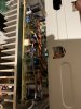
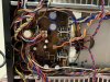
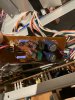
Making progress few photos power supplies and out main boards done as is the control amp board
Attachments

I’m close to doing a power up - I was reading some other threads and the user manual on the dc offset and I’m confused, am I correct in thinking that dc offset is done by
Step 1 positive probe to positive speaker terminal and negative probe to chassis ground
Step 2 positive probe positive speaker terminal red and negative probe to negative speaker terminal black
Step 1 positive probe to positive speaker terminal and negative probe to chassis ground
Step 2 positive probe positive speaker terminal red and negative probe to negative speaker terminal black
I can see the belt on the rear looks reasonably fresh so will leave it for now is there a recommendation what to use to live the white gears? I was thinking white grease?
I normally do these adjustments the other way round - in other words step 2 first.Step 1 positive probe to positive speaker terminal and negative probe to chassis ground
Step 2 positive probe positive speaker terminal red and negative probe to negative speaker terminal black
Don't forget that the Flat Amp adjustment will make a difference to the above, and also that you have to be mindful of the bias adjustment as well. It wouldn't be good to be tweaking the DC offset to perfection while the bias current is racing away and cooking your OP transistors.

So it's easy really, you need to have at least 2 hands and about 6 meters connected at the same time.

I normally do these adjustments the other way round - in other words step 2 first.
Don't forget that the Flat Amp adjustment will make a difference to the above, and also that you have to be mindful of the bias adjustment as well. It wouldn't be good to be tweaking the DC offset to perfection while the bias current is racing away and cooking your OP transistors.
So it's easy really, you need to have at least 2 hands and about 6 meters connected at the same time.
thanks Hyperion I can reverse the steps looks like I understood the manual correctly then following their steps…I might actually dial in bias first to protect the outputs I did change the trim pots so they’ll need adjustment…can then do the dc off set etc..I only have one meter maybe I should get a second one atleast to do the bias as quickly as possible to dial in
Do you normally do it with the heat sinks removed from the chassis?I put everything back together and front panel and realised it’s very tight to get to the resistors for bias adjustments with one meter let alone six lolI normally do these adjustments the other way round - in other words step 2 first.
Don't forget that the Flat Amp adjustment will make a difference to the above, and also that you have to be mindful of the bias adjustment as well. It wouldn't be good to be tweaking the DC offset to perfection while the bias current is racing away and cooking your OP transistors.
So it's easy really, you need to have at least 2 hands and about 6 meters connected at the same time.
No, fully assembled, I just find another way to make connections to the points required.Do you normally do it with the heat sinks removed from the chassis?
care to share?  id hate to damage it!
id hate to damage it!
The closest model to the 911DG that I have worked on was an AU-X711, and I don't remember any particular difficulty connecting to the measurement points. I do avoid testing or setting up an amplifier which is partially assembled as I feel this is asking for trouble.care to share?
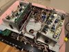
There might be less space in the 911dg than a 711 with the I couldn’t see any way possible to get to the resistors test points
Last edited:
Well good news! I did a power up and done the bias adjustment - output confirmed on both channels so very exciting!
DC offset was very close to spec on step 1
For step 2 for dc offset and the flat amp adjustment just to confirm is it correct to put the positive/negative probes to the speaker terminals like usual dc offset measurement?
DC offset was very close to spec on step 1
For step 2 for dc offset and the flat amp adjustment just to confirm is it correct to put the positive/negative probes to the speaker terminals like usual dc offset measurement?
Ok all adjustments done did an initial listen with my test speakers…when they sound good it’s a good sign! Few last photos adding zip tie cables where originals were - the small details make all the difference!
Attachments
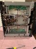

Few tips for anyone who wants to restore one of these - well covered in many threads here but to reinforce in case any doubt
1 - Change the trimmers
2 - fuse resistors on main amp module are 4.7 ohm and not 47ohm as the manual states
3 - when removing any cables be careful not to stress the joints I found lots of dry joints in my unit in these areas and any warmer spots
4 - route any cables back to original position especially around the power supply and front panel it’s easy to pinch wires and create shorts in these areas
5 - for wires soldered to the power supply board careful when moving that no metal points are touching to mitigate a short
6 - dc offset adjustment hot to cold step refers to the red and black speaker terminals step 1 is positive probe and negative probe to chassis
7 - repeat the bias and offset procedures twice to be sure
8 - when adjusting bias there is an orange wire close to the Trim pot it’s easy to touch this and create a short it’s a good idea to insulate this area and use insulated screw driver to mitigate touching a spot you shouldn’t
9 - be careful when ordering caps to measure their length the space available on the side of the dac is less than the other - longer caps will not fit in this space so measure the space and compare against the capacitor you want to order - same goes with power supply given it’s a tight space measure caps before assuming they’ll fit
10 - check as many solder joints as possible many look good but are heat stressed and will need reflowing
enjoy!
1 - Change the trimmers
2 - fuse resistors on main amp module are 4.7 ohm and not 47ohm as the manual states
3 - when removing any cables be careful not to stress the joints I found lots of dry joints in my unit in these areas and any warmer spots
4 - route any cables back to original position especially around the power supply and front panel it’s easy to pinch wires and create shorts in these areas
5 - for wires soldered to the power supply board careful when moving that no metal points are touching to mitigate a short
6 - dc offset adjustment hot to cold step refers to the red and black speaker terminals step 1 is positive probe and negative probe to chassis
7 - repeat the bias and offset procedures twice to be sure
8 - when adjusting bias there is an orange wire close to the Trim pot it’s easy to touch this and create a short it’s a good idea to insulate this area and use insulated screw driver to mitigate touching a spot you shouldn’t
9 - be careful when ordering caps to measure their length the space available on the side of the dac is less than the other - longer caps will not fit in this space so measure the space and compare against the capacitor you want to order - same goes with power supply given it’s a tight space measure caps before assuming they’ll fit
10 - check as many solder joints as possible many look good but are heat stressed and will need reflowing
enjoy!

pete_mac
Super Member
Nicely done sir!
Pretty sure those are non-inflammable resistors (NIR), as opposed to fuse resistors which have their own specific identifier (FR) in the service manual.
No real need to replace the NIR resistors unless they are faulty, but doing so isn't going to hurt anything.
2 - fuse resistors on main amp module are 4.7 ohm and not 47ohm as the manual states
Pretty sure those are non-inflammable resistors (NIR), as opposed to fuse resistors which have their own specific identifier (FR) in the service manual.
No real need to replace the NIR resistors unless they are faulty, but doing so isn't going to hurt anything.
T
you’re correct good pick up they are NIR and I used non flammable ones I should have used the correct term there
ThankyouNicely done sir!
Pretty sure those are non-inflammable resistors (NIR), as opposed to fuse resistors which have their own specific identifier (FR) in the service manual.
No real need to replace the NIR resistors unless they are faulty, but doing so isn't going to hurt anything.
you’re correct good pick up they are NIR and I used non flammable ones I should have used the correct term there