• The move to the new server is done. There are some software and database maintenance updates in process. This has us passing the hat around to help out. We appreciate any donations. Seriously, even a dollar helps. The payment page may be found here - https://www.audiokarma.org/support.html

Sansui AU20000 F-2508 board test point voltages?

jefferylhenr

AK Subscriber
Subscriber
Based on my success with my recent BA3000 project, I decided to get back to my AU20000. I am not getting +35/-35 on the f-2508 board. I have good rail voltages and the +/- 65 is spot on. The schematic has little or no test point voltages for the 35 volt section. I have been through this board multiple times and still no 35 volts output. Waiting on a couple ceramic resistors for r14 and R11 which are off board and 220 ohm 20 watts on the unit currently. I ordered 220ohm 25 watt which are the same size. This board is essentially the same as the BA3000 and I used exactly the same approach with no success. I have no shorts and the dim bulb is a good result.

Any test point voltages would be very helpful. I was able to find a thread on specifically the +35/-35 section of f-2508 which wanders around a bit but goes through the basic steps of trouble shooting. https://audiokarma.org/forums/index.php?threads/sansuii-ba-3000-problems.785942/page-4 …pages 4-9

I also found a recent very detailed walkthrough of an AU20000 restoration which is fantastic with detailed images and parts lists for each board. https://alexandrugroza.ro/vintageaudio/amplifier/sansui_au-20000/index.html
 
Register to hide this ad
So here is where I am at. I found R18 cooked so couldn’t read the color bands. The parts list indicates that it is a 10 ohm at R18 and I replaced it with a 10 ohm. I also replaced zd02 and tr15. I won’t get the 20 watt 220 ohm off board ceramics for a couple days, but will replace them as well as I understand they take quite a beating and measured one at 226 ohms and the other at 220.

I am in the process of doing a full restoration but want to get it running before I do that. It’s a 100volt unit and had numerous patch repairs through the driver boards and the outputs. And the fellow I got it from was running it on 120 volts with no step down xformer….

I have fairly well cleaned up that mess on the two sided f-2497 board which looked like someone had dumped a pile of spaghetti on it with all the patch jumpers. The f-2507 driver boards were also hard soldered in with no molex connectors and have replacement connectors on the way. Will make it much easier to remove and troubleshoot.

Right now, I just need to get the +35/-35 volts sorted. I should also add, the dbt indicates no shorts.

1708270568945.jpeg
 
Measure the voltage drop across each of the 220Ω resistors. The drop should be approx 26 volts.

A close-up photo of F-2508, both the component and conductor side, and one showing the location of the 220Ω resistors would be helpful.
 
Last edited:
The plus side tracks the negative side, so you have to fix the -35 volt side first, and the + side may be ok.
Lots of places to check. After verifying the voltage on the 220 ohm resistors, see if you have -15 on one side of Zd02, if not check voltages around TR04.
100 volt unit - build a 20 volt bucking transformer. 200 VA gets you 10amps @100 VAC. (if you haven't already)
 
I just completely restored this same f-2508 board in my BA 3000. These boards are essentially identical so I am now somewhat familiar with them. The +/- 65 volt section is working normally and it looks like the +/- 35 is pretty much the same circuit with a few small differences.

I am only seeing a few (-) mV at the -35 test pin and + 1.6v at the +35 pin. ZD02 a few mV and ZD01 15 volts. I have 71 volts at the collector of tr11 using the dbt and a few mV on tr16. The large 220ohm ceramic R11 is getting very hot and R14 is cold. So thinking it’s something on the negative side?

I assume the positive regulator mirrors the negative regulator, and won't get +35 until I get -35 volts. I also have some very good reference images of both the components and the traces. As far as I can tell nothing is installed wrong. But prior repairs weren’t the best workmanship.

But we shall see… what jumps out to your eyes.

I will get some shots tomorrow and post
 
The plus side tracks the negative side, so you have to fix the -35 volt side first, and the + side may be ok.
Lots of places to check. After verifying the voltage on the 220 ohm resistors, see if you have -15 on one side of Zd02, if not check voltages around TR04.
100 volt unit - build a 20 volt bucking transformer. 200 VA gets you 10amps @100 VAC. (if you haven't already)
Just a few mV on Zd02
 
The fact the +/-65V regulator is working confirms the supply voltage -85Vdc is ok. This means there should also be approx -85V on the supply side of R14 and at least -71V on the emitter (not the collector) of TR16. This means R14 should be warm.

If the 220Ω resistor at R14 is cold, I would check closely for a broken trace on F-2508 or a poor wiring connection either to or from the resistor where it is mounted on F-2512. It's not uncommon to find damaged traces or pads on F-2508 because of the heat.

Once you get voltage on the collector of TR16 this should bring the rest of the regulator back on line.
 
The fact the +/-65V regulator is working confirms the supply voltage -85Vdc is ok. This means there should also be approx -85V on the supply side of R14 and at least -71V on the emitter (not the collector) of TR16. This means R14 should be warm.

If the 220Ω resistor at R14 is cold, I would check closely for a broken trace on F-2508 or a poor wiring connection either to or from the resistor where it is mounted on F-2512. It's not uncommon to find damaged traces or pads on F-2508 because of the heat.

Once you get voltage on the collector of TR16 this should bring the rest of the regulator back on line.
 
Yes the wires to the off board 220 ohm ceramics R14/R11 were solid tinned copper and crystallized and would just break and I replaced them with 18 gauge multi strand already. And I already did a quick comparison measurement of Tr01/02 to 03/04. Can’t remember exactly what they were but they weren’t anywhere near 01/02 (albeit 20ish volts lower) it’s like they just aren’t getting power. Without tacking on test wires it’s all but impossible to get under the board to measure so I was just probing transistor and resistor legs back and forth. I will spend some more time today examining/measuring traces and solder point connections.

I am sure it’s something stupidly simple. But you know how it is once you have looked at something multiple times it’s easy to overlook things.
 
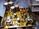
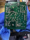
I did find some topsid photos on my phone, still need to get foil side. I suspect that whoever had this unit couldn’t get it to work as all the caustic glue is gone and lots of new parts. Nothing looks out of sorts 1013/2383’s etc and all the resistor values look and test to the schematic and transistors with proper orientation.
IMG_8402.jpeg
 
I think I am right when I say R14 & R11 won't get warm if the regulators don't 'start' - have you checked TR03 and TR04 lately, by this I mean removed them and checked them with a transistor tester? - also is ZD02 shorted? - only mV showing measured across it. (if you have replaced those transistors - what have you replaced them with? - they are quite beefy - 0.5A collector current).

Faced with a problem like this, I turn the board track side up and test every transistor and diode on 'diode test' range of my multimeter. Devices that you can't test because they are in parallel with others - they get removed and tested individually. If I can't find anything wrong I also test the resistors on 'Ω' range - and as you have a working board - make use of it for comparison checks. If the resistors are not obviously burnt they can still be open or high resistance without a mark on them. ;)
 
Last edited:
I think I am right when I say R14 & R11 won't get warm if the regulators don't 'start' - have you checked TR03 and TR04 lately, by this I mean removed them and checked them with a transistor tester? - also is ZD02 shorted? - only mV showing measured across it. (if you have replaced those transistors - what have you replaced them with? - they are quite beefy - 0.5A collector current).

Faced with a problem like this, I turn the board track side up and test every transistor and diode on 'diode test' range of my multimeter. Devices that you can't test because they are in parallel with others - they get removed and tested individually. If I can't find anything wrong I also test the resistors on 'Ω' range - and as you have a working board - make use of it for comparison checks. If the resistors are not obviously burnt they can still be open or high resistance without a mark on them. ;)
tr03/04 are the same as 01/02 1013/2383. I found a bad solder joint on r14 back to the jumper R34. Patched that and did what you described tracing everything back and through R11/14. I now have good continuity. Will test now.
 
Well making progress. I have 70ish volts on the emitters and bases of tr03/04 and 17 on the collectors. On tr16 I have e/c/b -2.4/-2.5/-3.1
 
there should also be approx -85V on the supply side of R14
Still keen to hear if you have -85V on the supply side of R14.

Voltages readings at other points in the circuit may be skewed by the lack of output from the series pass transistor TR16.

Regulation relies on there being a voltage output, i.e., there must be something to regulate.
 
Last edited:
Still keen to hear if you have -85V on the supply side of R14.

Voltages readings at other points in the circuit may be skewed by the lack of output from the series pass transistor TR16.

Regulation relies on there being a voltage output, i.e., there must be something to regulate.
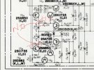
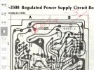
Here is what I measure at r14
1708389147820.jpeg
 
Back
Top Bottom