

You are using an out of date browser. It may not display this or other websites correctly.
You should upgrade or use an alternative browser.
You should upgrade or use an alternative browser.
Sansui AU20000 F-2508 board test point voltages?
- Thread starter jefferylhenr
- Start date


After some thought, everything behaves like the output is getting shorted to ground (R18 originally open, resistors r14 over heating). One possible is C 18 shorted, or solder bridge, problems with one of the other boards which uses the -35 volts, or something miswired that connects to the -35 volt line. The resistors are taking all the voltage, so the transistors are still probably okay.

Let me check that line of thinking.After some thought, everything behaves like the output is getting shorted to ground (R18 originally open, resistors r14 over heating). One possible is C 18 shorted, or solder bridge, problems with one of the other boards which uses the -35 volts, or something miswired that connects to the -35 volt line. The resistors are taking all the voltage, so the transistors are still probably okay.
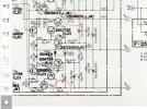
Considered that, but the resistors are large enough that even a shorted cap or zener wouldn't load the line enough to account for this problem. Also, did some checking, the -35 is used in a lot of the preamp board, and there are a couple of caps across them so lots of places for shorts to occur....May be out on a limb here, could you not remove the load on the -35v line by removing R602 on the F2496 board?
Marked D-D on the schematic. Also verify ZD601 and ZD602 15v zeners for shorts or opens.
We have a winner. Some one had put one of the little sidecar f-2498 boards in backwards. We have good +/- 35 volts now…After some thought, everything behaves like the output is getting shorted to ground (R18 originally open, resistors r14 over heating). One possible is C 18 shorted, or solder bridge, problems with one of the other boards which uses the -35 volts, or something miswired that connects to the -35 volt line. The resistors are taking all the voltage, so the transistors are still probably okay.
I tested the +/- 35 volt outputs and the negative leg showed a dead short. Pulled the output leads and one of the 4 leads was connected to the board that the f-2498 filter boards were attached to and noticed the right one was backwards, flipped it around to the correct position and the short was gone. Fired back up and boom, good +/- 35. While I had everything opened up I went ahead and recapped the entire front end as most of the boards just pop out.Good find!
Now back to the amplifier section. I am getting close to having this one up and running. I have already rebuilt the protection board, both amp modules and I was able to find the proper headers and connectors to replace the hard soldered legs between the f-2507 driver boards and the f-2512 interconnect board which makes it almost impossible to remove them for access, parts swap outs and testing.

richardpp
Well-Known Member
I saw this same mistake recently in another thread. AU-20000 Troubleshooting.
Sounds like you're on your way, now. The new molex connectors will make life much easier
Sounds like you're on your way, now. The new molex connectors will make life much easier
I installed the new 25 watt r14/r11 220 ohm ceramic resistors. Probably a bit overkill but the fit just fine. You can also see I installed molex connectors for easy removal of the output transistor modules/heat sinks.
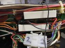
I do have a question, we’re these fly back diodes installed on the underside of the f-2508 power board transistors tr05/10 a service bulletin?
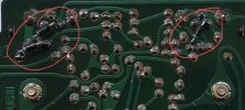
And… are there published service bulletins for the AU20000 and does anybody have them?
Finally first power up and I have good bias stability and control. DC offset good as well. There are no shortcuts to bring these back to life. Most of the struggle was cleaning up prior butchering and hacks. Sounds incredible

One of the lessons learned is add fusing to all the main power connections to the power filters. These caps hold their charge essentially forever. Working on these is like walking on a mountain top in a thunderstorm holding a lightening Rod. It’s not a matter of if.. it’s when.
Don’t even touch anything inside without disconnecting all six power leads.
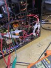
Don’t even touch anything inside without disconnecting all six power leads.

That's a very good addition, if there is a major fault with the high current rectifiers for example, it could do some serious damage. (The line fuse is the only protection for those rails, and especially if its value is incorrect, i.e. too high, it presents a significant hazard). As regards stored charge, you could add some bleeder resistors - these are often seen in Sansui amplifiers, 3.3KΩ being a common value.One of the lessons learned is add fusing to all the main power connections to the power filters.

Second what John suggested. If you use a 3.3K bleed resistor positive side of the cap to ground it would take approximately two minutes to discharge the main cap to a volt or less. Will admit that it only takes once lighting off those big power caps with inadvertent application to ground of metal objects to dissuade one from experiencing it again.
For fun I ran the bleed formula on the 7000 that came with bleed resistors installed. With cap supply voltage about 60v and cap value of 3300 ohm Sansui used a 12k resistor for a bleed down to 1 volt time of about three minutes on the main power supply cap. Note that higher resistance slows the time to zero and reduces the load on the resistor in watts. I like the 1watt metal oxide resistors here. As a side note Sansui cap coupled amps also commonly use the same setup on the output coupling caps, however the values often change. In the case again of the 7000 Sansui used 150ohm 5 watt cement resistors on 3300uf caps giving a much faster bleed down time of under three seconds. Sunday rambling about concluded
For fun I ran the bleed formula on the 7000 that came with bleed resistors installed. With cap supply voltage about 60v and cap value of 3300 ohm Sansui used a 12k resistor for a bleed down to 1 volt time of about three minutes on the main power supply cap. Note that higher resistance slows the time to zero and reduces the load on the resistor in watts. I like the 1watt metal oxide resistors here. As a side note Sansui cap coupled amps also commonly use the same setup on the output coupling caps, however the values often change. In the case again of the 7000 Sansui used 150ohm 5 watt cement resistors on 3300uf caps giving a much faster bleed down time of under three seconds. Sunday rambling about concluded
Second what John suggested. If you use a 3.3K bleed resistor positive side of the cap to ground it would take approximately two minutes to discharge the main cap to a volt or less. Will admit that it only takes once lighting off those big power caps with inadvertent application to ground of metal objects to dissuade one from experiencing it again.
For fun I ran the bleed formula on the 7000 that came with bleed resistors installed. With cap supply voltage about 60v and cap value of 3300 ohm Sansui used a 12k resistor for a bleed down to 1 volt time of about three minutes on the main power supply cap. Note that higher resistance slows the time to zero and reduces the load on the resistor in watts. I like the 1watt metal oxide resistors here. As a side note Sansui cap coupled amps also commonly use the same setup on the output coupling caps, however the values often change. In the case again of the 7000 Sansui used 150ohm 5 watt cement resistors on 3300uf caps giving a much faster bleed down time of under three seconds. Sunday rambling about concluded
I secured and got the fuse wiring nicely ordered. I have 5 amp fast blow AGC fuses in it now and they seem to be high enough rated. What I don’t like is Sansui used 80 volt caps but the rails are at 85? I am going to up the power filters to at least 100 volts. Haven’t been able to find the correct size yet. As for the bleeders, I thought about that but then wasn’t comfortable with having the full charge discharge cycling every time it was turned on and off. I guess you could remove them once all the work is complete.That's a very good addition, if there is a major fault with the high current rectifiers for example, it could do some serious damage. (The line fuse is the only protection for those rails, and especially if its value is incorrect, i.e. too high, it presents a significant hazard). As regards stored charge, you could add some bleeder resistors - these are often seen in Sansui amplifiers, 3.3KΩ being a common value.
I have everything working nicely except for the meters. Is there an anything to know about adjusting the pots on the meter board? Of course I need to pull the face back off again…
Yes they do.. This one didn’t have any. It also had the driver boards hard soldered to f-2512. I was able the find connectors and headers. Thinking with a Japan only issue they cost down everywhere possible. It’s missing all kinds of parts.Just curious - the schematics for both the BA-3000 and AU-20000 show 3.3K resistors across the main filter caps...

I made these up to put across the power filters. 3.9k ohms and 4.7 uf 3,000 volt poly caps.