Looks fine to me - I am very pleased for you!Here are the results of the variac testing of the secondary windings @Hyperion .


Looks fine to me - I am very pleased for you!Here are the results of the variac testing of the secondary windings @Hyperion .


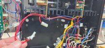
Yes, I think so, if the short were C-E, but probably not if B-E for example.Any outputs shorting to ground would also cause a DBT fail, even with the driver amps isolated, right?

Many thanks, very helpful.@Hyperion is correct, a C-E short will fail the DBT even with the driver amps isolated.
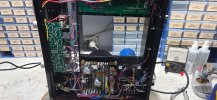
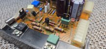
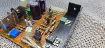
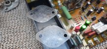
You can quick-check the output transistors for C-E shorts without removing the heatsink assemblies by probing the transistor case (C) together with the orange wire on the output board (E) shown in your last photo above. Because the transistors are in parallel you only need to test one to test all three, so test one of the NPN's on the front side of the heatsink and one PNP on the back, for each heatsink.
To properly isolate the load from the unregulated supply when testing with a DBT, disconnect terminals 7 and 8 (output stage) and 29 and 30 (driver stage) on F-2511.
Just saw your last post re: shorted outputs. Old uniwatt pre-driver transistors a common cause for shorted outputs.
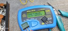
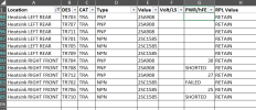
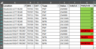
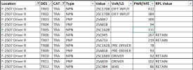
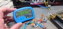
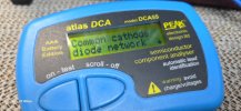
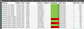
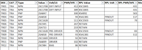
The shorted ones, literally shorted all 3 (CBE) leads. The failed one registered as a diode so one side was open.Just wondering what your failed criteria is in the above chart? If it helps I have 1 spare 2SA908 and 1 spare 2SC1585.
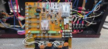
R34, R35 and /or R36, R37 on driver board usually show signs of overheating with shorted output transistors.
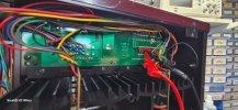
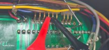
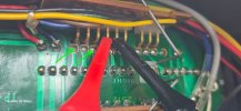
I get 1.17Ω at left bias test points and 1.14Ω at the right.Suggest you switch the meter to read resistance between the bias test points. Power off. You should see a reading of ~1.2 Ω. (0.47 +0.47 + lead resistance). If not, an emitter resister might have gone open.
You can also check whether or not the driver board is providing sufficient voltage to turn on the output transistors by measuring voltage to ground at each of the two points shown below. First remove the connector board F-2510. Start with the bias trimmer set full CCW and adjust up. If all is well, a positive or negative voltage of approximately 500mV should be achievable using the bias trimmer and any discrepancy between positive and negative readings should be able to be nulled using the dc-offset trimmer.
Hope this helps.
View attachment 3831297
Good call.Be careful... keep the DBT in circuit, in this situation you may find the bias situation may recover without sending you a memo.