

You are using an out of date browser. It may not display this or other websites correctly.
You should upgrade or use an alternative browser.
You should upgrade or use an alternative browser.
Sansui BA-3000 blowing mains fuse following restoration
- Thread starter BradWil
- Start date


richardpp
Well-Known Member
That all looks good.
I didn't specify, but around 90V at TM01 unloaded, so around 70V if loaded looks good.
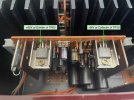
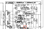
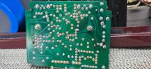
Suggest checking for voltage either side of R16 10Ω on F-2508. Not sure if you have access to R16, you may need to remove the board to check it. Otherwise check for a broken trace on F-2512.
I didn't specify, but around 90V at TM01 unloaded, so around 70V if loaded looks good.
Suggest checking for voltage either side of R16 10Ω on F-2508. Not sure if you have access to R16, you may need to remove the board to check it. Otherwise check for a broken trace on F-2512.
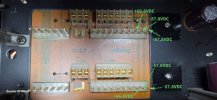

F-2508 R16 measures 10.2ΩThat all looks good.
I didn't specify, but around 90V at TM01 unloaded, so around 70V if loaded looks good.
Suggest checking for voltage either side of R16 10Ω on F-2508. Not sure if you have access to R16, you may need to remove the board to check it. Otherwise check for a broken trace on F-2512.
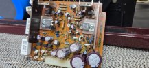
View attachment 3831726
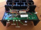
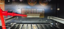
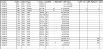
Voltage to GND on the TR10 Collector side of R16=-66.2VDC
Voltage to GND on the rail side of R16=3.2mVDC
DBT on.
Drivers removed.
richardpp
Well-Known Member
The problem is on F-2508, there should be approx 66V on both sides of R16. I’ll need to check the schematic …..F-2508 R16 measures 10.2Ω
Voltage to GND on the TR10 Collector side of R16=-66.2VDC
Voltage to GND on the rail side of R16=3.2mVDC
DBT on.
Drivers removed.
richardpp
Well-Known Member
Ok I see this is a little more complicated than I thought.
I'll lay out what I'm seeing so far, someone else might be able to help.
You can't bias the amplifier because the negative 65V regulated voltage supply is not reaching the connections on F-2512 where the driver boards plug in.

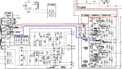
The regulator board F-2508 has ~80V on the input.
The negative side of the regulator has -65V on the output of the series pass transistor but after R16 this falls to within a few millivolts.
The positive side of the regulator has +65V on its output which goes directly to the driver boards.
Since the positive side of the regulator tracks the negative side, if after R16 the voltage is effectively 0V, why doesn't the positive side also read 0V?
I would be interested to see if -35V is missing as well. Can you see a connector for the meter boards that might let you test the regulated 35V supply?
I'll lay out what I'm seeing so far, someone else might be able to help.
You can't bias the amplifier because the negative 65V regulated voltage supply is not reaching the connections on F-2512 where the driver boards plug in.
The regulator board F-2508 has ~80V on the input.
The negative side of the regulator has -65V on the output of the series pass transistor but after R16 this falls to within a few millivolts.
The positive side of the regulator has +65V on its output which goes directly to the driver boards.
Since the positive side of the regulator tracks the negative side, if after R16 the voltage is effectively 0V, why doesn't the positive side also read 0V?
I would be interested to see if -35V is missing as well. Can you see a connector for the meter boards that might let you test the regulated 35V supply?
Last edited: