• The move to the new server is done. There are some software and database maintenance updates in process. This has us passing the hat around to help out. We appreciate any donations. Seriously, even a dollar helps. The payment page may be found here - https://www.audiokarma.org/support.html

Sansui JPD adventure

GrisPato

Super Member
Today my first JPD Sansui arrived. It was really slow here in the Netherlands with nice defect Sansui amplifiers so started looking in Japan.
I have an au-d707 on a ship coming. But today arrived my last purchase as the first with FedEx.
Sansui au-d907, no output.

20210617_125755.jpg

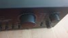
Clean faceplate, not a scratch.
Volume knob wurried me a little. . .
20210617_125817.jpg

Turned out to be mostly dirt, is not as shiny as I know they can but is ok.

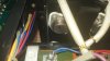
Fitted with original outputs
20210617_130947.jpg

Will be the first action when I have time. Replace them with Onsemi's during repair/ restore time and pray they are going to test good!
From the top everything is a little dusty and sticky. From the bottom looks really clean.

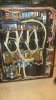
20210617_131229.jpg

20210617_131245.jpg 20210617_131249.jpg 20210617_131235.jpg

The only negative upto now is that the volume pot makes a metallic scraping noise when turned.
So could be broken. As a positive could be the reason there was no output and as far as I can see I can replace it with an alps rk 27 or a TDK volume pot.
Looking forward to work on this one!!!
 
Register to hide this ad
You could recondition it using Leestereo's wonderful thread for the AU-919. :)

I am for sure going to use that as a compass.
I have on the way 2 au d707 and an au d-907 limited. These are all three a little less good looking but all working.
Because I care less about the looks in detail my plan was to use one au d707 for if I need parts like transistors. One au d707 for my son, if needed with replacement transistors ( to be reasonable sure I have enough good ones for the d907's.) And the d907 Limited for myself, totally upgraded.
And this one to pay for them all.
Here in the Netherlands they like original state. So I am going to start to get it working, remove glue and first just replace faulty components as much as possible with original ones from the other 3 amps. I don't want to have a discussion with potential buyers which way is better. An they can always come back for the repairs ;).
 
Last edited:
I have had the benefit of doing a full on rebuild of an AU-919, and then 'upgrading' it with the suggestions in Leestereo's thread with just a few tweaks of my own added in. The difference is very noticeable indeed and really takes the AU-919 to the next level. I actually did this twice, once to a customer's AU-919 and once to my own AU-919 because I was so impressed with the results.
 
Very nice! Doesn't seem to be too much glue, excellent score! Look forward to seeing the progress.

I have a guide here as well which is very heavily based off of LeeStereos guide. It's a hefty amp, lots going on.

https://audiokarma.org/forums/index.php?threads/au-919-recap.932305/

Thanks!
I think I read your thread once, especially the replacement of the filter capacitors. I will for sure use this as a guide together with Leestereo's. I have sometime to prepare the work.
As mentioned in my before post: a little wurried about having to convince potential buyers that it is better to restore with the opportunity to upgrade. I am selling my au 719 at the moment and get people asking if it still sounds like a Sansui?!? A lot of people are convinced that the engineers were busy making a compilation of specific brand and make of all components toake there sound instead of circuit design and ofcourse quality components. So is sad to put all the effort in when it looks like most people don't appreciate it. I responded to one potential buyer that I still have all the components that came out and that minus the defective ones I could put them back for him. And that I was willing to repair it for him down the road. He didn't respond!!
I am for sure going to do this with the d907 Limited and one of the d707's, even considering practicing with changing out the output transistors for some modern TO3P like the C3263/A1294 on the d707. Just to build a little stock of the nmc/nma 1216.
 
By the way, I was planning to use some onsemi mj replacements during restoration. Would it hurt if I use the Inchange variant:
MJ 15022 ISC Transistor NPN TO-3 200V 16A 250W.
I can blow up three of them ☺️ and still have some change left compared to the onSemi's
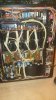
 
Was looking at the pictures (had to close it up again for the time being) and noticed all of a sudden the connectors of the transformer to the power supply board are hanging there loose.
20210617_131245.jpg

The purple and yellow wires. Could be even a better explanation why there was no sound!?
Can't wait to find out . . .
 
Was looking at the pictures (had to close it up again for the time being) and noticed all of a sudden the connectors of the transformer to the power supply board are hanging there loose.
View attachment 2262102

The purple and yellow wires. Could be even a better explanation why there was no sound!?
Can't wait to find out . . .
Good catch! Those red WIMAs don't look original on the MC head amp either. Other than that, it looks pretty original to me.
 
The purple and yellow wires. Could be even a better explanation why there was no sound!?
Can't wait to find out . . .
Yes, those are the high current AC feeds to the main rectifiers, if you plug those in, I strongly recommend powering up on DBT, but you could also do some multimeter checks with power off looking for shorts first.
 
I strongly recommend powering up on DBT, but you could also do some multimeter checks with power off looking for shorts first.
Yes yes yes!!!
I even don't have my step down yet. I ordered three of them. Went with 1,5 kVA. Mostly because of included inrush current limiter and the price difference was just €23 each with an 1 kVA without the limiter.
First am going to take out the outputs and measure them replacing with mj's.
First just powersupply. Would love to find a safe way of measuring leakage of the filter capacitors with the full voltage applied. I would prefer not to open those cans if it's not necessary.
 
@Hyperion
Would value your opinion on using the Inchange TO3 during restoration.
Like I mention price difference is big and they are not going to be used in the end.
It's a really good idea, but I have noticed how careful you are with this stuff so you might be able to get away with not doing so. ;) If you have a working set of original output transistors, and with the amplifier as discovered in an unknown condition, I would probably do it, just for peace of mind.
Would love to find a safe way of measuring leakage of the filter capacitors with the full voltage applied.
You could (somehow :dunno:), connect a low value resistor (less than 10Ω) in series with either the positive or negative of each main capacitor, and measure the voltage drop across the resistor (recommend doing this 'off load'), I=V/R and you have it.
 
Last edited:
Do you think this would be worth it? Or would capacity / esr value give enough information about status of the capacitor?
I know the new/better against old/ original capacitor is a touchy subject for some.
I don't think in such extremes. Often both positions have validity.
For example: some people mention life expectancy of 1000-5000 hours. But if you read the spec sheets you can see that often under 40° C this can go up to as much as 40000 hours. Especially the filter capacitors don't dry out that fast. And I think will depend a lot on usage. Electrolytic capacitors form there oxidation layer under potential. So the more regular it was used the better it will stay formed. Ofcourse this is all information we don't have. For that the desire to also test there leakage.
May be I should get a Variac to give them a basic reform.
 
you might be able to get away with not doing so. ;) If you have a working set of output transistors, and with the amplifier as discovered an unknown condition, I would probably do it, just for peace of mind.
Hahaha,
I better don't push my luck. Anyways, I shorted at least one output myself on my d55x, chasing my own tail.
Learning to better be safe then sorry in some things.
I still don't label wires and connectors because it forces me to study the topology of the wiring which I think is important to be able to follow when you are repairing equipment. Takes more time but is valuable.
 
May be I should get a Variac to give them a basic reform.
In this particular case a short time on a DBT should be more than enough 'reforming'. I don't have a sophisticated capacitor tester, just ESR & Value. When assessing main filter capacitors for replacement, I measure the ripple voltage of the main rails with everything set up properly, (no signal) and also the tendency of the rails to 'sag' under load (with signal), this gives a Real World idea of how they are performing in my opinion.
 
When assessing main filter capacitors for replacement, I measure the ripple voltage of the main rails with everything set up properly, (no signal) and also the tendency of the rails to 'sag' under load (with signal), this gives a Real World idea of how they are performing in my opinion.
I read something recently about this. You giving advice to measure ripple, something like 50 mV being good, up to 100mV acceptable. Understand that, measuring the job they are in for!!
Just will have to get an understanding of the functioning of my scope o_O.
Thanks a lot for sharing your knowledge and expertise!
 
Back
Top Bottom