

You are using an out of date browser. It may not display this or other websites correctly.
You should upgrade or use an alternative browser.
You should upgrade or use an alternative browser.

Alex22
Well-Known Member
I hope it arrives soon. I sometimes have items arrive in country and then have to wait 4 to 5 weeks for then to deliver it, outrageous!
Oh and could you please stop with Japanese domestic versions, I don't want to go the 'step down' route.
I can resist anything except temptation......
Where did you put those 2sk389?
Did you use an extra board?
That's correct...there was no much free space on those boards...so I did another very small board which has only the two cascoded 2SK389 on it...and that board connects in the place of original JFET. A bit elevated from the amp input board, but there was no other way. And since I had those spare 2SK389 laying around....couldn't resist to not tweak it

My initial intention was to open a thread for it..but some other things appeared....so priorities changed.
There were more tweaks done on control/flat amp board, and I mean not just recapping.
It took some months to sing again

Last edited:

GrisPato
Super Member
I had to push a little bit,at least it's through customs. Paid, and now should be here in a few days.I hope it arrives soon
Yes, big temptations on yahooauctionjapan!!
Control / flat amp related tweaks - changed op-amps to NJM2068LD, various caps here and there, added a CCS (there is just a R by default) and some additional RC filtering for the LTP, multi-turn trimmers for DC-offset adjusting, some connectors to make the boards easier to connect/disconnect.....AU-D77X is a pain to work on due to all those boards hard-wired between them....if you don't add enough connectors to plug/unplug easy, you'll swear....been there 

P.S. Hope to have something interesting for you to see sometime next year jan-feb
P.S. Hope to have something interesting for you to see sometime next year jan-feb
Last edited:
Alex22
Well-Known Member
Great news.I had to push a little bit,at least it's through customs.
Yes, big temptations on yahooauctionjapan!!
Too much information dammit................

JoseHH
Super Member
John - it's like below drawing, tried to do a high-level one to be easier to understand. However, that "virtual GND" is not used for any high-current path, nor for any biasing as far as I can figure it out. So why those resistors are there, what and why are they trying to "isolate" from GND.....no clue
Could it be that the 10Ohm resistors are just to provide a current path for the protection network?.
I one removes the 10 ohms resistor then the Zobel network will have a different cut-off frequency, and probably will not work at all because they are designed to pass a considerable AC current and this current has nowhere good to go via the two 6K8 resistors. So the 10 ohm resistor isolates the delicate the reference point (node between the two 6k8 resistors) from the noisy chassis ground, yet it allows enough currents to pass through the Zobel networks to the power supply. In the presence of an AC current through the Zobel networks the mid point between the two 6K8 resistors will wiggle around by the voltage drop in the 10 Ohms resistors, so a small value resistor is important.
But then I ask why didn't they use a 10 ohms resistor between the mid point of the 6K8 resistors and chassis, and short the Zobel networks directly to the power supply center tab without sharing current with the reference point. I don't know.
EDIT:
No currents to chassis, they should return to the power supply.
Last edited:
Exactly what I was thinking.But then I ask why didn't they use a 10 ohms resistor between the mid point of the 6K8 resistors and chassis, and short the Zobel networks directly to the power supply center tab without sharing current with the reference point. I don't know.
I would add than in a "normal" functioning state, the zobel is not carrying any significant current, unless there are some oscillations...which is not "normal" anymore. But the zobel presents a moderate-to-low impedance to the amp at higher frequencies, however. At least this is how I see it.
I am really curious how Sansui implemented there ground free circuit!
I found in my notices something related to AU-D907G Extra PSU - that is has individual and separate dual-secondaries for the power + driver stage. Don't remember where I got that conclusion from, but at least for AU-D907F Extra this is true. Possible extrapolated at that time from that one - if so, it could prove to be wrong, however
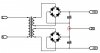
.Like the below circuit - that red-circled point it's called "floating ground" because there is no galvanic (or "direct") connection between that GND point and the transformer windings. No charging currents are flowing to / from that GND point, so it's obviously "cleaner" than a "normal" GND connected to the center tap of the secondary winding.
However, the speakers are still connected to that point because that's the GND, we are talking about SFF topology in this case. So not the same concept as later "ground free" Alpha's / X-Balanced topology.
But still can't figure out where those mR99 10R resistors fit in the picture
You'll have the opportunity to confirm whether this is true or not - looking forward to that

Regards
GrisPato
Super Member
Yes, board F-3573 carries the dual powersupplys for small signalboards and the inputstage from the driverboard F-3678.
There is even a unpopulated provision for an extra rectifier and two capacitors. May be they wanted dual rectifiers for the small signalboards to but decided not to do it?
By the way, PSU for the F-3678 is not regulated, it was for the AU-D907F.
And on another subject. After studying some more pictures of different amplifiers I noticed that Sansui regularly used the extra electrolytic's (220uF), like in the AU-D707, on the main filtercapacitors on 707/607 models even into the alpha models.
There is even a unpopulated provision for an extra rectifier and two capacitors. May be they wanted dual rectifiers for the small signalboards to but decided not to do it?
By the way, PSU for the F-3678 is not regulated, it was for the AU-D907F.
And on another subject. After studying some more pictures of different amplifiers I noticed that Sansui regularly used the extra electrolytic's (220uF), like in the AU-D707, on the main filtercapacitors on 707/607 models even into the alpha models.
By the way, PSU for the F-3678 is not regulated, it was for the AU-D907F.
I'm not 100% sure about that
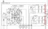
At least from the manual that I have for AU-D907F Extra, input or driver stage from the power-amp section (board F-3678) has a "normal" (un-regulated) power supply. I don't have any data for AU-D907F, so I can't say anything about that model. Maybe your comment was referring strictly to that one (a.k.a non-Extra model). The two red areas concern the PSU outputs to the F-3678 board, in case of AU-D907F Extra.
GrisPato
Super Member
Yes is was. Or better said I think it is.Maybe your comment was referring strictly to that one (a.k.a non-Extra model).
For.what I can see the AU-D11 is the international version of the AU-D907F.
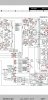
Also found the use for the rectifier+2caps. Was used for the MC-headamp and the F Extra and G Extra use a transformer for the MC.
It seems that this change happened at the last moment.
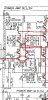
Another deviation from normal practice is the shunt capacitor for the zenerdiode in the positive local regulator for the LTP. Normally this is 100uF, here it's 470uF. I can not recall seeing this in earlier or later models.
Last edited:
 Too many versions...
GrisPato
Super Member
Ok,
Couldn't resist . .
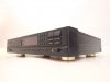
Have been keeping an eye on a TOTL CDplayer from Sansui.
This one doesn't look so special.
Then I went looking for some info.
I found this:
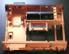

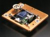
Brass feet, isolation transformer on the digital output ( will have to find more information about that). So doesn't look so simple anymore.
So I made a bid and won it.
Really curious how this is going to end!
Couldn't resist . .
Have been keeping an eye on a TOTL CDplayer from Sansui.
This one doesn't look so special.
Then I went looking for some info.
I found this:
Brass feet, isolation transformer on the digital output ( will have to find more information about that). So doesn't look so simple anymore.
So I made a bid and won it.
Really curious how this is going to end!
Last edited:
Alex22
Well-Known Member
So I made a bid and won it.
That is super cool looking. Can't wait to seeing more.
GrisPato
Super Member
Two packages arrived the 24 of December 2021 in Den Haag the Netherlands by ship. Waiting for a week for our Royal Dutch Post to handle this in the busy Christmas period I started asking for information.
The only response I got were non-answers: they are with Customs, bla,bla.
After four weeks I started to get worried and made a phonecall.
They would make an internal inquiry about where they were.
After 5 days I got an answer: the packages are missing! Sorry!
No solution nothing. So, Dutch postal laws see the sender as the client from the postal company.
So I sended a mail to the proxy service I am using to put an inquiry with Japan Mail.
This week both package came in by surprise mail, no notification, nada.
With an apology sticker on the box.
Benefit is that they forgot to tax it with VAT and handling cost. So in the end the waiting saved me around €100.
One of the packages was another AU-D707 that I won and wanted because it had a manual with it. Sadly it is an owner's manual not a service manual.
Second package are some stepdowntransformers.
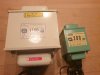
Nissyo, the big one I wanted for the bench but have to say looks mighty impressive. Just for scale a second picture.
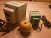
Weight of the 1100 VA is at least 9-10 kg and I am first going to compare it with the toroidal stepdowntransformer.
The small one was intended for the AU-777 but that one has a multivoltage transformer. So could be handy for the CA-606.
But, let's see if somebody notices what is wrong?
The only response I got were non-answers: they are with Customs, bla,bla.
After four weeks I started to get worried and made a phonecall.
They would make an internal inquiry about where they were.
After 5 days I got an answer: the packages are missing! Sorry!
No solution nothing. So, Dutch postal laws see the sender as the client from the postal company.
So I sended a mail to the proxy service I am using to put an inquiry with Japan Mail.
This week both package came in by surprise mail, no notification, nada.
With an apology sticker on the box.
Benefit is that they forgot to tax it with VAT and handling cost. So in the end the waiting saved me around €100.
One of the packages was another AU-D707 that I won and wanted because it had a manual with it. Sadly it is an owner's manual not a service manual.
Second package are some stepdowntransformers.
Nissyo, the big one I wanted for the bench but have to say looks mighty impressive. Just for scale a second picture.
Weight of the 1100 VA is at least 9-10 kg and I am first going to compare it with the toroidal stepdowntransformer.
The small one was intended for the AU-777 but that one has a multivoltage transformer. So could be handy for the CA-606.
But, let's see if somebody notices what is wrong?
GrisPato
Super Member
Yep, the little one is 120-100V.
I was looking anxiously at that time to get some stepdowntransformers. Following 7 - 8 of them. I didn't check the pictures well enough on all of them.
So I made a bid and I won.
Then I checked the pictures . . . To late.
I had the option to just leave it at the proxy and they would discard of it.
But decided I would be a good reminder to check images well so I kept it.
I could get a 230-120 V stepdown, just would need a 200-300 VA so the cost is small.
I was looking anxiously at that time to get some stepdowntransformers. Following 7 - 8 of them. I didn't check the pictures well enough on all of them.
So I made a bid and I won.
Then I checked the pictures . . . To late.
I had the option to just leave it at the proxy and they would discard of it.
But decided I would be a good reminder to check images well so I kept it.
I could get a 230-120 V stepdown, just would need a 200-300 VA so the cost is small.

Dan75
Active Member
That's why I started this. To do something like that. Although not adjusting an amplifier but to build one for myself.
I have an AU-D77X. Could be an option to try something like you did. Later on when I understand more of it myself.
Will take some years, have to learn a lot still, I am not in a hurry.
Thanks for sharing. Would love to see a thread about it, maybe in DIY or solid state, although it's lik a selfmade allpha 607 Mo's limited, it could fit in exclusively Sansui.
Hi, I saw a D77X locally at a thrift store but noticed that the switches (Disc selector switches, AUX etc.) on the right side won't stay engaged. Are you familiar with this, is this an easy fix or is
it something like a snapped off piece of plastic inside the switch.
Tried internet for info on this but so far came up with nothing, nor parts, exploded view or images of the switches on the inside of the unit even.