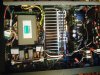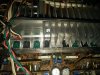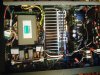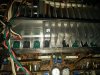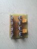
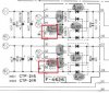
Yep, there are 2 separate bridges for power stage, one for each channel and then continuing with the separate filtration per channel to make it like a dual-mono. Both bridges are connected to the same secondary - being that the trafo has only one wiring

This helps for a better separation, since the most of crosstalk happens at higher currents - at least in theory.
PSU for input & drive stage was also changed to a better voltage regulator instead of default basic R + Zener.
To exchange output BJT's to MOSFET's you have to modify:
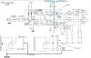
1 - Vbe multiplier or bias spreader circuit, to make for higher voltage on it due to higher Vgs for MOSFET's compared to Vbe of BJT's. Basically there's a single resistor to be increased, you can see this one on any MOS amp
2 - modify the resistor between drivers emitter's (or outputs gates / bases), depends how much current you want to give them. From my perspective, Sansui are "cooking" the drivers in MOS amps a bit - which I don't like. So I increased that resistor a bit
3 - change the resistors from BJT's bases because they are too small (4.7-10R), you need larger values for MOSFET's there (27+47R)
4 - obviously replace BJT's with the MOSFET's
And kind of that's it, nothing outstanding if you ask me

There is no need to change the pre-drivers or the drivers - also Sansui themselves used the same ones between "normal" amps (with BJT) and MOS versions. Didn't tried yet, but the only (I think minor anyway) gain would be to change the drivers for a higher Ft ones, like 2SC5171 and 2SA1930. But I don't expect "miracles" due to this - and it's also possible to need adjusting the compensation caps due to higher Ft, so this should be done with care and with proper equipment to check afterwards.
Hope I answered your questions








 . Bring the AU-D907G