

You are using an out of date browser. It may not display this or other websites correctly.
You should upgrade or use an alternative browser.
You should upgrade or use an alternative browser.

GrisPato
Super Member
I bought five amplifiers, three still on the way. I hope I can populate at least three of them with good ones because they all use different versions of the nm lapt devices. The other are going to get modern TO-P3 devices installed.What transistor did you use as replacement to NMA1012/NMC1012 and NEC B537?
I have the same issue with my 907 blown OP transistor, two NMA1012 and one NMC1012 and one NEC B537.
I went this way because it's impossible to know what is on sale from the Sanken nm transistors on the market is real.
Found another alternatives for 2SC1845 & 2SA992 used in DD stage --> 2SC2459 & 2SA1049. 607 and 707 series from MR generation mentions them and they indeed seem to be used on the driver board pcb, while for 907 series only 2SC1845 & 2SA992 are listed:Found some used as an alternative to c1845 / a992 although not in the diamond differential stage.
607MR

707MR

907MR
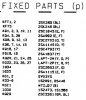
And - most probably - the alternatives were also used in AU-A607 MOS Premium, judging by their case in the photos:
607MR driver board
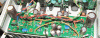
and 607MOS Premium
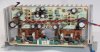
Regards
GrisPato
Super Member
Interesting find. This means Sansui used several low noise small signal transistors in the diamond differential stage. Although it seems they choose mostly the c1845/a992 in the TOTL model. Found in the datasheet that this one has a max power dissipation of 0,2 W, even less than the c2240/a970. So I am going to assume that the c2240/a970 are going to be ok in that regard. This could also give some indication that Sansui was not giving to much importance to transistors giving the sound signature as it should not be depending on that.
@fojica
I really appreciate the work you're putting in to this details.
@fojica
I really appreciate the work you're putting in to this details.
GrisPato
Super Member
Thanks,
I had a look at that document before. Sadly most of the subs are not available these days anymore.
GrisPato
Super Member
Had some time to finish the driverboard F-2839 just leaving the driver transistor tr32 sb537 that shorted together with the outputs for later when I receive my d707 to use for replacement parts.

Nothing exciting happening there. Removed the electrolytic caps to remove the glue and the caps. Removed all black flags and replaced with C0G ceramics.
I am using Leestereo's restoration thread as a guide and that was interesting for me.
This is an earlier production model: October 78. And Sansui changed quite a few things here.
First on both models is included on the board and components list with the board picture, two for each channel electrolytic caps decoupling the rail for the driverstage. These are not in the schematic. Interesting is that on my version they are positioned behind the heatsink for the driver/ bias transistors and on the later model, one is also on the outside behind heatsink but the two on the inside of each channel are now inside the heatsink on the board. They changed places with the base resistors for the outputs on that side. I also noticed they moved the inductor coil further from the heatsink. And I remembered reading I think on amp8's site that he had one of these driverboards where the coil was shorting to the heatsink.
Further c39-42 are in the older board noble polystyrene not black flags and c57-60 decoupling film capacitors are also present.
This means they made a reasonable amount of adjustments and even designed a new version of the board.
Next up the headamp and flatamp boards.
Nothing exciting happening there. Removed the electrolytic caps to remove the glue and the caps. Removed all black flags and replaced with C0G ceramics.
I am using Leestereo's restoration thread as a guide and that was interesting for me.
This is an earlier production model: October 78. And Sansui changed quite a few things here.
First on both models is included on the board and components list with the board picture, two for each channel electrolytic caps decoupling the rail for the driverstage. These are not in the schematic. Interesting is that on my version they are positioned behind the heatsink for the driver/ bias transistors and on the later model, one is also on the outside behind heatsink but the two on the inside of each channel are now inside the heatsink on the board. They changed places with the base resistors for the outputs on that side. I also noticed they moved the inductor coil further from the heatsink. And I remembered reading I think on amp8's site that he had one of these driverboards where the coil was shorting to the heatsink.
Further c39-42 are in the older board noble polystyrene not black flags and c57-60 decoupling film capacitors are also present.
This means they made a reasonable amount of adjustments and even designed a new version of the board.
Next up the headamp and flatamp boards.
Last edited:
GrisPato
Super Member
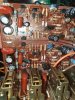
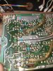
Had some time just before family vacation ( back already ) to work on the flat amp board F-2841. Replaced all 10 black flags with ceramic C0G including the six on the back of the board. Still have no idea why some have these, some have four, some none?
Glue eat one of the legs of the film coupling capacitor C17, change them both for 0,47 polypropylene from Panasonic. Just left to do now the are the decoupling capacitors C23-30, the film caps glued to the electrolytic's.
Also started with disassembly of the volumepot. I will post more about that in my thread about pots and switches.
Last edited:
GrisPato
Super Member
Today two more amplifiers came in from Japan.
First one AU-D707!


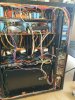

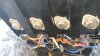

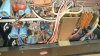
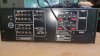
Looks good, very woolly inside on the driverboard. Some light scratches on the top of the faceplate but not to eye-catching.
What really impressed me is that iron inside! That transformer is giant. Really something you have to see in real. Outside dimensions are 140 x140 x 120 mm.
Outputs are not shorted so that could be ok. Top cover came with just two screws and it looks like something on the chassis bended. Can't get it to fit in right angles but is going to work out fine.
I popped out the driverboard/ heatsink in a minute. Is really easy although the wiring on this one is a little tighter than on the AU-D907.
Is back in his box waiting for his turn.
First one AU-D707!
Looks good, very woolly inside on the driverboard. Some light scratches on the top of the faceplate but not to eye-catching.
What really impressed me is that iron inside! That transformer is giant. Really something you have to see in real. Outside dimensions are 140 x140 x 120 mm.
Outputs are not shorted so that could be ok. Top cover came with just two screws and it looks like something on the chassis bended. Can't get it to fit in right angles but is going to work out fine.
I popped out the driverboard/ heatsink in a minute. Is really easy although the wiring on this one is a little tighter than on the AU-D907.
Is back in his box waiting for his turn.
GrisPato
Super Member
Then my second AU-D907 Limited.
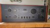
This one had some bad storage time.
Powerswitch a little stuck, speakerselector switch totally stuck, can not move it at all by hand.
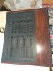
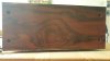

The rest of the exterior doesn't look to bad. But will need a good cleaning.
Then the inside. . .
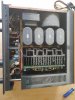
Took a microfiber cloth and cleaned it up a little. Could not put him back in the box looking like that.
No black flags inside, all polystyrene Noble!
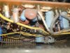
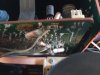
And no shorted outputs! So that is looking good!
Also back in the box for later.
This one had some bad storage time.
Powerswitch a little stuck, speakerselector switch totally stuck, can not move it at all by hand.
The rest of the exterior doesn't look to bad. But will need a good cleaning.
Then the inside. . .
Took a microfiber cloth and cleaned it up a little. Could not put him back in the box looking like that.
No black flags inside, all polystyrene Noble!
And no shorted outputs! So that is looking good!
Also back in the box for later.

GrisPato
Super Member
Used one of the transistors from the newly arrived au-d707 for the driver transistor that was shorted on this au-d907.
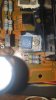
So while I also finished the volumepot disassembly and cleaning the driverboard can go back. Than installing the test outputs and it can be tested! Hope to be able to get to that this week
So while I also finished the volumepot disassembly and cleaning the driverboard can go back. Than installing the test outputs and it can be tested! Hope to be able to get to that this week

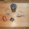
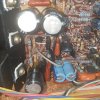

Bumpalump
Well-Known Member
There is no reason to change original outputs tranaistors if they are working fine in my opinion
About capacitors condition, capacitance and ESR is one thing, second is leakage, you can measure their D factor and measure AC voltage at main rails, a ripple under 10-50mV is bery good, above 100mV will give tou a reason to change capacitors
About capacitors condition, capacitance and ESR is one thing, second is leakage, you can measure their D factor and measure AC voltage at main rails, a ripple under 10-50mV is bery good, above 100mV will give tou a reason to change capacitors
GrisPato
Super Member
I am replacing them whit the 2SA1068 / 2SC2493 because two of them are shorted and I want the same transistors in the output. I am assuming they are very similar but because there are no specifications for them. The six good ones I can use for my AU-D707 which has to shorted to.There is no reason to change original outputs tranaistors if they are working fine in my opinion
About capacitors condition, capacitance and ESR is one thing, second is leakage, you can measure their D factor and measure AC voltage at main rails, a ripple under 10-50mV is bery good, above 100mV will give tou a reason to change capacitors
I first was considering replacing the outputs on one 907 Limited to TO-P3 and use the originals as replacement. Because I thought before that they used the same Sankens in the AU-D707 / D907 and D907 Limited. But as you probably know they are all different.
Because Kale had some stock I preferred to keep things "original".
Regarding the main filter capacitors: I will keep them in when, like you say ripple is sufficiently low. For now, what I measured, most of them measure good for capacitance and ESR accept in one of my D707's where there are two that measure high in ESR and about half in capacitance (700mOhms; 8000uF instead of 14-15000uF). Ripple measurements will tell if the ones measuring good are up to the job.
There is a lot I have to learn and I am missing equipment to do it right. So for now I will have to work around that a little. Work with what I have. In the cleaning of the pots and switches I like to start with minimal tools so I can learn. Test equipment sadly gets really expensive fast because you go into professional quality territory, which in a way I don't need because I am not going to measure all day every day.
Still trying to find out what is really needed and what not.
GrisPato
Super Member
Finally found the time ( or better: made time) to finish the F-2835 board.
First had to remove some more resistors to clean the glue of them and had to order some more C0G 22pF to replace the "black flags". Decided to order some extra!
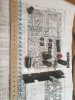
Decided also to get some filter caps for the AU-D707's because on both of them they were measuring bad, to make the order worthwhile and before there is no stock!

Let see if I can get that all in there again today
First had to remove some more resistors to clean the glue of them and had to order some more C0G 22pF to replace the "black flags". Decided to order some extra!
Decided also to get some filter caps for the AU-D707's because on both of them they were measuring bad, to make the order worthwhile and before there is no stock!
Let see if I can get that all in there again today
GrisPato
Super Member
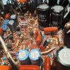
Made it!
F-2835 is ready and back in.
12 black flags replaced with C0G ceramic capacitors.
Removed all E.C. capacitors, and glue touched components, removed glue from board and components, measured capacitors : all good!
So all back on the board.
Assembled the chassis again because this one will have to wait for a little.
I am getting some serious interest on the AU-D707 so I am going to start on one of them now.
Will start a new thread for that one.

StirFriedFrp
Member
Looking forward to the thread about the AU-D707! With special interest, because the serious interest came from me