• The move to the new server is done. There are some software and database maintenance updates in process. This has us passing the hat around to help out. We appreciate any donations. Seriously, even a dollar helps. The payment page may be found here - https://www.audiokarma.org/support.html

SCA-35, phase splitter mod

JesusJones

Well-Known Member
Recently set up a SCA-35 (with efb and bypassed tone controls) and it sounded different than I remembered (or maybe the same....). Anyways, I took another look at the schematics and boards and came up with a plan. Ditch the positive feedback, balance the phase splitter and give it a new screen dropping resistor. Some others have tried something similar with claimed success and it makes sense.

You need some wire and 1M resistors. Remove the 120K, parallel it with the 27K to get your 22K for the tail. Lift the cathode end of the 1uf and tie it to ground. Add a 1M from the B+ 320V to the 1uf pentode screen connection. That's all, it sounds more true to the source material, flatter and less fatiguing to me. It could probably use more feedback, but I'm not equipped to properly dial that in.

Pretty easy to accomplish without doing any permanent changes. Separating the 1uf cap from the signal path is what really helps. The circuit should be balanced stock but the 1uf cap doesn't truly let that happen, it ultimately adds distortions in the lower frequencies.
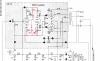
sca-35 mod.png


Let me know if you try. Also, if you can get the open loop gain (after this mod) please share it.
 
Register to hide this ad
Just a few comments...

First, the stock parts list for the SCA-35 doesn't show a 1uF capacitor. Which cap did you "separate from the signal path"? Second, positive feedback in this circuit increases driver gain about 10dB. That gain is lost when the components are removed. Many contemporary sources are pretty high level and can undoubtedly drive this without issues, but MM phono hasn't changed much since the '60s. I assume this is the one input where the modification would be most likely to create level difficulties. Have you measured the overall sensitivity of the amplifier at 1 kHz in phono mode? Finally, have you or the others you mentioned made measurements regarding headroom or distortion before and after this modification? It's not unusual in this hobby to hear a group of people crow about audible improvements, only to discover later that performance was actually degraded. I'll just add that you are at a significant disadvantage if you're not able to tune the feedback. It has changed significantly by virtue of these modifications.

In case you haven't seen it, here's an article that discusses the 7199, alternate pentode-triodes and positive feedback:

https://www.angelfire.com/electronic/funwithtubes/pentode-triode.html

Jack
 
The parts list does show C18 to be 1 uF. See page 19 of the Instructions: http://www.thehistoryofrecording.com/Manuals/DynaCo/Dynakit_SCA_35.pdf

From the attached RCA Application Note for the 7199 (see pages 4 and 5) it follows that the original arrangement in the SCA-35 could create frequency dependent feedback, increasing the lower audio frequencies (the frequency at which this feedback becomes effective depends on the value of C18). The modification would undo this, which doesn't seem like a good thing to me.

When the cathode resistor of a pentode is not decoupled, like in the SCA-35, it is good practice to connect the decoupling capacitor for the screen grid to the cathode, so not to ground.
 

Attachments

the original arrangement in the SCA-35 could create frequency dependent feedback, increasing the lower audio frequencies (the frequency at which this feedback becomes effective depends on the value of C18). The modification would undo this, which doesn't seem like a good thing to me.
The goal was to undo any of those frequency dependent effects it may have on the phase splitter. Effects like, positive feedback and uneven loading of the splitter. Mostly though, I don't like the idea of positive feedback being fed "globally" through the 2 stages that make up the splitter. You generally don't go looking for ways to add positive feedback loops, unless forced to. I see it as a generator of odd harmonics/IM disortion that no amount of gain and NFB will ever fix correctly, however slight they may be.
When the cathode resistor of a pentode is not decoupled, like in the SCA-35, it is good practice to connect the decoupling capacitor for the screen grid to the cathode, so not to ground.
That's a change I will make then. I am curious why its done that way. Is it mostly because it helps keep the screen voltage better referenced to the changing cathode? or is there more to it?
MM phono hasn't changed much since the '60s. I assume this is the one input where the modification would be most likely to create level difficulties. Have you measured the overall sensitivity of the amplifier at 1 kHz in phono mode? Finally, have you or the others you mentioned made measurements regarding headroom or distortion before and after this modification?
I only use the power amp section so no phono concerns for me. No measurements either, just going by theory, a bit of theories and ear, for now.
 
honestly if the goal is no tone controls and no phono you'd have an easier time just converting it to an ST-35 and leaving the volume control and selector in place. Less hassle with sourcing tubes too, a 7247 is somewhat more available.
 
honestly if the goal is no tone controls and no phono you'd have an easier time just converting it to an ST-35 and leaving the volume control and selector in place. Less hassle with sourcing tubes too, a 7247 is somewhat more available.
It's even better, 7247 AKA ECC832 is in JJ new production.
And yes i agree converting to ST-35 is a simple matter of replaing 2 boards ( and keeping
the possibility to revert to a SCA-35 if parts are kept)
 
That's a change I will make then. I am curious why its done that way. Is it mostly because it helps keep the screen voltage better referenced to the changing cathode? or is there more to it?

Yes, it keeps the screen grid voltage referenced to the cathode voltage like it should be. As far as I know, there's nothing more to it.
 
you can reference it to ground or cathode. If you tie it to ground, it actually introduces a bit of local feedback at that point since the screen voltage won't track with the cathode voltage. More common to see it tied to cathode but Fisher did run it to ground on the early TA-600 with the 7199, and I've done it with an amp I modified. That one had grid leak bias and a circuit board. I modified it for cathode bias but tying the screen cap to cathode would have involved a lot more PCB hacking than I was willing to do so I left it alone. It had too much gain anyway so having a bit of degenerative feedback in the pentode wasn't exactly a problem.

That one was an EF86 and I forget what small triode. Electrically it was the same as a 7199, just in two tubes.
 
Attached are the schematic of the Mullard 5-20 and a relevant part of the explanation of the schematic (pages 473 and 474 from "Valve Amplifiers", 4th Edition, Morgan Jones). The Mullard 5-20 doesn't have its cathode resistance decoupled completely and there's GNFB applied to the non-decoupled part of the cathode resistor.

If I understand the explanation correctly, referencing the screen grid capacitor to ground will introduce positive feedback to the screen grid.

page 473.jpg

page 474.jpg
 
Last edited:
The parts list does show C18 to be 1 uF. See page 19 of the Instructions: http://www.thehistoryofrecording.com/Manuals/DynaCo/Dynakit_SCA_35.pdf
LOL, the first site I happened to see has it listed incorrectly as 0.1uF.
https://www.nostalgickitscentral.com/dynaco/products/schematics/sca35.pdf
Sorry abut that, I thought it had to be true if it's on the Internet. Actually, I searched a little more, and it turns out this is a well-known error that has propagated.

Jack
 
When the cathode resistor of a pentode is not decoupled, like in the SCA-35, it is good practice to connect the decoupling capacitor for the screen grid to the cathode, so not to ground.
I have done this both ways with the EF86 and found little or no difference. In fact, I typically bypass the screen to ground, and distortion is extremely low.

Regarding positive feedback and its potential for distortion, this should all be considered in context with the overall distortion of the amplifier. Stage-by-stage distortion accumulates as the square root of the sum of the squares. So, a preamp at 0.05% driving a power stage producing 0.5% results in a total output distortion of 0.503%. This is nearly all produced in the output stage. If for no other reason than this, I would recommend caution before modifying the original design, particularly if it's not possible to measure total distortion or to tune the NFB loop afterward.

Jack
 
OK, I think I see what I did now.
If I understand the explanation correctly, referencing the screen grid capacitor to ground will introduce positive feedback to the screen grid.
That is how I read it too, it got me thinking and I believe it is wrong. I ran some simulations, with a screen cap to ground vs to the cathode (when the there is no cathode bypass). There is more gain when tied to the cathode. There is less gain when it is tied to ground. This agrees with what gadget said as well.

Knowing this, and recounting what the angelfire article says, I now realize I removed both a NFB loop from the splitter and local PFB from the gain stage. The 120k supplies NFB back to the screen and tying the screen cap to the cathode is what provides PFB. I originally thought the 120k was to supply screen voltage from the cathode AND PFB to boost the gain. But it was actually NFB, if I understand things correctly now. But I did accomplish my goal, of removing some PFB and balancing the splitter, but in a totally back acewards way. No harm done yet though, so lets keep trying.

I would recommend caution before modifying the original design, particularly if it's not possible to measure total distortion....
Boring ;):music: I trust my ears enough for my purposes. But yes, I will need to acquire some square waves to really dial in whatever design I land on.

Time to reassess a little.
 
Last edited:
I don't know LTspice or other simulation software (and want to keep it that way for now since it forces me to dive into things deeper). So I give it a go using my methods.

I look at the situation in which the control grid goes more positive.
As a result, the voltage difference between control grid and cathode goes down.
The plate current goes up (making the plate voltage go down because of the rising voltage drop over the plate resistor).
The unbypassed cathode resistor makes the cathode voltage go up because of the rising voltage drop over the cathode resistor.
This causes the voltage difference between control grid and cathode to rise to a lesser degree than it would when the cathode resistor would be bypassed.
The above is a description of the negative feedback mechanisme of an unbypassed cathode resistor.

The situation with the screen grid capacitor connected to the cathode:
The voltage difference between cathode and screen grid stays constant.
Conclusion: There is no feedback mechanisme going on at the screen grid.

The situation with screen grid capacitor connected to ground:
The voltage difference between ground and screen grid stays constant.
The voltage difference between cathode and screen grid reduces since the cathode voltage rises.
Reduced voltage difference between cathode and screen grid in a pentode makes the plate current rise to a lesser degree than it would when the voltage difference between cathode and screen grid would be constant.
This reduced rising of the plate current means that the cathode voltage rises to a lesser degree because of the reduced voltage drop over the cathode resistor.
But this means that the amount of negative feedback gets reduced.
Conclusion: There must be positive feedback going on since the negative feedback developing over the unbypassed cathode resistor gets counteracted.
 
I think we both found the same thing, but look at it from a different reference point. "One says positive looking from the outside, one says negative looking from the inside. Both are right, but they always fail each others quizzes in school"

In my mind, g2 voltage is something that is held constant. You plot your load and bias lines onto the static g2 chart. The bias line is your NFB voltage. The pentode performs as stated (in the charts) for a given g2 voltage and without simulation tools that is your reference point.

With the cap tied to ground

you try to make g2 stay constant and you can treat it like a triode with an unbypassed cathode, NFB

screen cap to the cathode
you start actively shifting g2, this ultimately causes there to be more gain. The NFB voltage is being used for PFB to the screen. Is it PFB? NFB reduced??

I'm not sure whats actually correct to think, but I believe the same thing is happening in the end.
 
I find it difficult to understand what you mean. So I just leave it to this for now: The curves in datasheets on pentodes, are (almost) all based on the voltage between the cathode and the screen grid being constant. This condition is surely met when the screen capacitor is connected to the cathode since it keeps the voltage between the screen grid and the cathode constant. But this condition is not met in circuits in which the screen grid capacitor is connected to ground while the cathode voltage varies, which is the case when the cathode resistor is not bypassed (completely). It causes the cathode to screen grid voltage vary.

What tool did you use to simulate the circuit?
 
EL504 just beat me to the post, but I would echo his ideas. With the screen decoupling cap tied to ground, the g2 voltage fluctuates the most with respect to the cathode. All voltages in the tube are measured relative to the cathode. So a "constant" screen voltage (relative to the cathode) is best achieved by using an adequate decoupling cap tied directly to the cathode.
 
Last edited:
Theorizing performance isn't the same as measuring it. Anyone designing an amplifier stage should be in possession of all the facts. No one here who has failed to actually compare differences in gain and distortion for conditions of bypassing to ground vs. bypassing to the cathode has the authority to make a valid judgement. I'll add that LTSpice, which I use extensively, is only as good as the models. Operational differences can sometimes be significant, and one cannot simply substitute a simulator for real-world performance, particularly in the context of advising fellow audiophiles about how they should build.

Jack
 
I never did measurements on this myself. But I can't really deduce from your post #11 what your measurements exactly told you, except that the differences in measured distortion seem to be very small and that you have a preference for decoupling the screen grid to ground.

In my post #3 I just wrote, based on what I have seen in trusted designs and trusted literature (as far as I can judge), that good practice is to decouple the screen grid to the cathode when the resistance in the cathode lead is not, or just partly decoupled. In my later posts I just tried, with my limited abilities, to explain/justify this good practice.
 
Gentlemen if I may try to add some clarity:

For a pentode vacuum tube, either the control or screen grid is an inverting input into the device, as a positive going signal at either of these elements produces an inverted (negative) signal at the plate. The cathode is a non-inverting input, since a positive going signal at this element produces a non-inverted (positive) signal at the plate.

Applying these facts to a conventional pentode stage (without any external feedback applied) we get:

1. With both the cathode and G2 held at AC ground potential (both AC bypassed to ground), then maximum gain is produced from the stage when a signal is applied to G1. In this case, it matters not whether the low end of the G2 bypass cap is connected to the cathode, or grounded.

2. If there is no G2 bypass cap in the above scenario, then gain is reduced because a signal is now developed across the G2 dropping resistor, and exists between G2 and ground. The signal generated at G2 is opposite in phase to that applied to the control grid G1. With G2 being an inverting input, and having an opposite phase signal (relative to G1) applied to it, it works against the signal applied to G1 so gain is reduced. The signal at G2 then represents a NFB signal.

3. If there is a G2 bypass cap present and it is connected to ground, but there is no cathode bypass cap (not held at AC ground), then there will be a feedback signal developed across it as well. The cathode signal certainly acts to reduce the potential between G1 and the cathode, but also between G2 and the cathode as well, so it is also a NFB signal. The only difference between this scenario and scenario #2 is that in #2, the cathode was head steady while a NFB signal was present at G2. Here, G2 is held steady while a NFB signal is present at the cathode relative to G2. The loss of gain is typically greater in this scenario because the NFB signal impacts both G1 and G2, whereas in scenario #2 it is only acting on the signal present at G2.

4. Connecting the G2 bypass cap to the cathode but still not using a cathode bypass cap will increase the gain from scenario #3 above, because now the NFB applied relative to G2 has been eliminated, but is still present with respect to G1.

In all of these scenarios, there is no positive feedback to aid amplification -- only negative feedback that that can detract from the maximum amplification that the stage is capable of. The above descriptions are for a self contained pentode stage. Adding a global NFB loop doesn't change anything described above. It simply reduces the gain of the stage it is inserted into in the usual manner.

With respect to the Mullard 5-20 design where part of the cathode resistance is not bypassed -- it simply become a version of scenarios #1 and #4, where most of the cathode resistance is bypassed, but not all of it. In that case, the stage itself will generate a small amount of NFB across the unbypassed section as described in #4, but generate most of the gain of which it is capable as described in #1, because the majority of the cathode circuit is bypassed. The insertion of global NFB across the unbypassed portion of the cathode circuit then reduces the gain of the stage as described above.

I hope this helps!

Dave
 
The curves in datasheets on pentodes, are (almost) all based on the voltage between the cathode and the screen grid being constant
Yea I was looking at it wrong, thanks for keeping at me. Rethinking things with this in mind, the comment that Dave made, sums up everything (and more!) that I am trying to better understand. I'm gonna let it all soak in a bit and reassess, again, lol. Thanks, everyone

What tool did you use to simulate the circuit?
I use ltspice, it certainly works well enough for peering into a topologies inner workings. And can save you a lot of soldering time if you like tinkering.
 
Back
Top Bottom