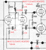
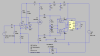
Before I published my latest work on the SCA-35 (Hidden Treasure: Bringing out the Very Best of Dynaco's SCA-35), I did an extensive amount of work regarding the SCA's driver circuit, with the idea of trying to determine which alternate tube would be the best substitute for the 7199. During the course of that work, one of the exercises was to determine differences in gain produced from the circuit from the use of different tube types.
One of the first things I set out to determine was what was the actual amount of GNFB applied to the amplifiers, since (rather uncharacteristically) Dynaco makes no mention of it either in the published specifications, or in the Technical Description of the circuit provided in the Owners Manual. Virtually every other vacuum tube power amplifier from Dynaco offers that specification (usually in the Technical Description), but not so with the SCA.
While many integrated amplifiers may use a "water downed" version of a basic power amplifier offering -- as in (for example) using less GNFB to help achieve the full gain requirements that integrated amplifiers need -- such is not the case with the SCA-35. Being as old school as I am, I'm not much of a modeling guy, but I do measure a lot. With that in mind then, the measured GNFB level of the SCA is 20 db -- just as it is in the SCA's stripped down cousin, the ST-35. I was really quite impressed when I measured that amount of GNFB in the design -- but there is a catch that will be mentioned shortly.
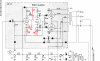
With the input sensitivity well established at 0.15 vac at the input of the power amplifier boards, and 20 db of GNFB in place, some quick calculations will show that the pentode stage of the driver tube in the SCA actually operates with a voltage gain on the order of about 769. This is achieved with the pentode stage operating with a conventional (i.e. w/o PFB) gain of 243 (very close to Jack's modeling), that is then elevated by 10 db of PFB. These are all numbers produced from measurement -- but as mentioned earlier, there's a catch.
To make my measurements, I took a good but discarded PC-10 board as a stand alone piece, and first fully populated it with components that were within 1% of their specified value. This also included the coupling caps and grid return resistors for the output tubes as well. Next, the board was modified as follows:
1. The inputs into the two GNFB networks were grounded. This wasn't really necessary with the capacitive loop, but was important with the resistive loop to ensure DC integrity was maintained at the pentode's cathode terminal.
2.The closest output tube socket was wired to accept a 6CG7/6FQ7 tube, whose sections were paralleled. The plates were connected to the same B+ source powering the driver tube, the grids connected directly the cathode of the splitter, and the cathodes went to ground through a 22k 1W resistor. A coupling cap and 1Meg discharge resistor were hung on the cathode output of this output buffer to serve as the output of the board, so that this tube then drove all the measuring devices, and could do so without any concern for loading down the cathode output of the splitter (eliminating the need of providing an exactly identical load on the plate side as well). As in the original build then, the splitter's outputs only "see" their normal coupling caps and output tube grid return resistors -- identical loads on each output, since the input impedance of the buffer that is directly connected to the splitter's cathode has basically an infinite input impedance. Finally, a heater balance network was provided as well to also mimic the original design. Because of the very low drive impedance of the signal generator used, hum and noise proved to be insignificant in the test, even though the circuit board was out in the open on the bench.
3. The modified board was powered from my Heath bench power supply, adjusted to provide 6.30 vac at the tube heater terminals, and 320 vdc for the tubes to operate from, just as they do in the original design.
4. I used a 1 kHz sine wave test signal applied directly to the input of the board, at precisely 1.5 mV -- the low level to ensure that the output always remained undistorted because of the very high gain available from the circuit. For the purposes of determining the true gain displayed, the output levels as presented here are first divided by 92% to account for the loss of the buffer output stage, and then the resulting figure is divided by the input signal level of .0015 vac to determine the gain developed. In other words, by first dividing the output level by 92%, it then produces an accurate value as would be measured at the cathode of the splitter if a measuring device of infinite input impedance were available.
Using these test conditions, I used 4 brand new never used RCA 7199 tubes and one Raytheon branded 7199 tube. I used these tubes to repeat my earlier tests that I did for the article, because it was just easier to repeat the test than it was to try and find all the notes from my original work. The results were quite interesting. First the measured gain amounts, and then some comments representing my conclusions. The numbers are all RMS values. The output voltages are as appeared at the output of the buffer output stage. The first four tubes are RCAs, while the last is the Raytheon:
Tube #1: Output Voltage = 1.22 vac / 92% / .0015 = Gain of 884.
Tube #2: Output Voltage = 1.70 vac / 92% / .0015 = Gain of 1232.
Tube #3: Output Voltage = 1.56 vac / 92% / .0015 = Gain of 1130.
Tube #4: Output Voltage = 1.20 vac / 92% / .0015 = Gain of 870.
Tube #5: Output Voltage = 1.46 vac / 92% / .0015 = Gain of 1058.
Conclusions -- there were so many from these results, and other observations made:
1.The circuit is quite obviously very tube example sensitive.
2. All of these tubes can easily produce the aforementioned 20 db of GNFB in an operating amplifier, with tubes of higher gain (of course) producing proportionately more GNFB.
3. In my original tests, GNFB levels ranging from 19.5 db to 23.0 db were encountered from different tubes tried. To the design's credit, it took the higher levels of GNFB very much in stride, showing no tendencies towards instability.
4. The circuit is quite sensitive to the B+ level used as well.
5. The circuit is also quite sensitive to the value of the pentode's cathode resistor. Dynaco specified a 5% tolerance for this part. It's unbelievably important! With a value of just + 20%, I was easily and repeatedly seeing gain levels for the pentode section of over 5000 with some tubes!!
6. Gain variations of up to +140% were hardly uncommon. (I originally tested about a dozen or so tubes as I recall. The tubes used for this test were all new and not part of the original testing, but basically prove out the wide variation noted in the earlier tests.)
7. Because of the high open loop gain the pentode section produces with the PFB connection, and the target 20 db of GNFB employed, the circuit does a decent job of holding the required input level relatively stable that's required to produce full power output -- in spite of the wide variation in tube gain. In other words, rather than the input sensitivity moving around, it's the GNFB level that primarily varies with the varying gain levels produced from different tubes.
8. The varying gain levels -- and therefore GNFB levels -- affects measured amplifier performance, and at least by way of damping, can affect sonic performance as well.
9. Is it any wonder that Dynaco decided not to mention the level of GNFB employed in the SCA-35? While Dynaco used the 7199 a lot, the SCA is the only design of theirs using it with PFB.
10. Because of all this nonsense (said affectionately), this circuit will test the limits of any modeling program or modeler!
Is it a neat little circuit? -- no doubt. Does it do a good job of stabilizing the splitter section's operating point? It sure does. Does it work well as designed in practice to deliver solid power amplifier performance? Amazingly so. But good golly miss Molly, the variation in gain produced from one tube example to the next is quite significant -- let alone the variations capable of being produced by the other variables mentioned as well. It's almost like the great country song lyrics that state: I wish I didn't know now what I didn't know then! Dynaco apparently designed the circuit so that the typically least performing example of the 7199 could still meet the basic distortion specifications for the unit, and for those units with "hotter" tubes installed -- hey, so much the better, since the circuit seems to take it all in stride. If all of this says anything, it once again speaks remarkably well of the output transformers employed.
Final conclusion, as is always the case with virtually any scientific endeavor, working to squeeze more and more performance out of an amplifier, engine, or whatever will always produce more and more quirks and potential instabilities. Because of the inclusion of the "magic elixir" PFB, so is it the case with this circuit as well, with the effects of PFB likely taken to their maximum practical extreme.
All of this will either stir the pot, or blow the flame out -- but that's the results and conclusions from all my testing of the circuit for anyone so interested to analyze and ponder.
Dave
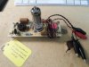
A quick pic of the AC Gain Tester I used to run the tests of the SCA driver circuit -- bagged and tagged so that I'd remember what the silly thing was when I look back on it in the future. The single tube installed is the 6CG7 output buffer -- built into one of the original output tube sockets to isolate the driver circuit from the outside world. The little ceramic cap that can be seen located to the upper left of the 7199 socket is the cap used in the capacitive GNFB loop -- normally located over by the outside output tube socket, but now relocated to this position so the input to the cap could be easily grounded. The clip leads allow for easy connection to the bench power supply, and little wire studs were installed in appropriate board eyelets to provide for the easy connection of input and output leads via the test equipment's own clip leads. With all the original tests done now, the tester continues to have an ongoing purpose for practical use by allowing me to quickly and easily test and install tubes of nearly identical AC gain to match the performance of the two channels.






 Dave
Dave