• The move to the new server is done. There are some software and database maintenance updates in process. This has us passing the hat around to help out. We appreciate any donations. Seriously, even a dollar helps. The payment page may be found here - https://www.audiokarma.org/support.html

SCA-35, phase splitter mod

Gentlemen if I may try to add some clarity:
.....
I hope this helps!

Dave

Thank you for your post. But it doesn't help me yet because I can't figure out what is wrong with my attempted explanation in post #13. Could you perhaps point out the step(s) in my attempt that is/are wrong?
 
The situation with screen grid capacitor connected to ground:
The voltage difference between ground and screen grid stays constant.
The voltage difference between cathode and screen grid reduces since the cathode voltage rises.
Reduced voltage difference between cathode and screen grid in a pentode makes the plate current rise to a lesser degree than it would when the voltage difference between cathode and screen grid would be constant.
This reduced rising of the plate current means that the cathode voltage rises to a lesser degree because of the reduced voltage drop over the cathode resistor.
But this means that the amount of negative feedback gets reduced.
This is all correct, but the effect of g1-k and g2-k both changing gives you two sources of NFB, and despite the "reduced voltage drop over the cathode" there is still more NFB than if only g1-k were changing (screen cap tied to cathode). This was where things got confusing for me too once you reminded me everything is relative to the cathode.
screen cap to the cathode
you start actively shifting g2, this ultimately causes there to be more gain. The NFB voltage is being used for PFB to the screen. Is it PFB? NFB reduced??

The correct thinking here then would be NFB reduced. There is no PFB being added, just Vg2-k being stabilized. I also still believe that that p.427 explanation is out of context or sort of wrong.
 
Last edited:
EL -- The only point I would disagree with your analysis on is the conclusion you came to for the situation you discuss when the G2 bypass cap grounded. It is basically the same situation I describe in my scenario #3. In your analysis, you conclude that there must be positive feedback going on since the amount of negative feedback developed by the cathode resistor is reduced (versus when connected to the cathode). It is not that there is positive feedback present to reduce it but rather, that it's the amount of negative feedback that's present between the two scenarios. Therefore, it's a question of degree, as in to what degree NFB is present.

Recall the last sentence in my description for scenario #3, wherein I say:

"The loss of gain is typically greater in this scenario because the NFB signal impacts both G1 and G2, whereas in scenario #2 it is only acting on the signal present at G2."

The amount of "local" feedback present within a stage is directly related to the un-feathered OLG (open loop gain) of the stage. For this discussion, that would be the amount of gain present as described in my scenario #1, where the stage is operating at maximum gain. Anything that causes that gain to be reduced (from other bypass cap configurations) then must be a form of NFB being applied to the stage.

With an un-bypassed cathode resistor and the G2 bypass cap connected to ground -- there is more NFB taking place because the NFB present at the cathode is affecting both G1 and G2. Therefore, the gain of the stage -- based on bypass cap configuration -- is further reduced and with that, so is relatively the cathode NFB signal itself, because it is a product of the gain of the stage in the first place. Since the gain has been reduced, so must be then the NFB signal it can create at the cathode.

With the G2 bypass cap connected to the cathode, then the NFB can only affect G1. Relative to this comment, your assessment is that the reduced NFB when the G2 bypass cap is grounded must be because of some element of positive feedback taking place in that scenario to reduce it. The correct thinking is that when the G2 bypass cap is grounded, it is allowing more NFB to take place because it is impacting both G1 and G2 and with that, the amount of NFB that could otherwise take place, is reduced as well.

I hope that helps.

Jesus -- I completely agree -- the assessment Jones made regarding the Mullard 5-20 design is -- with all due respect -- either mis-characterized, or simply wrong.


Dave
 
I deleted an earlier post in this spot due to errors. After analyzing Jones' statement further, I suspected that he indeed made an error. However, there are a number of factors involved in this, and it's necessary to know the magnitude of all the interrelationships before reaching a final conclusion. Some of the math for this is complex and falls into areas I haven't considered previously, so I decided to simulate the circuit in SPICE and make relative gain measurements.

As it turns out, gain of the stage with G2 bypassed to the cathode is greater than when it is bypassed to ground. This implies that, contrary to Jones' assertion, G2 feedback is in fact negative when connected to AC ground. I also admit that a cursory examination of all the phase relationships appears to bear this out. On the other hand, GNFB applied to the cathode passes through a 3.9K resistor, and it must be considered that connecting the G2 bypass to this point might create secondary effects that account for the difference in gain. That's particularly true considering that the difference is only about 0.5dB.

In the end, I can only confirm the difference in overall performance of the stage. I'm not prepared to state categorically that Jones is incorrect regarding G2. And to be honest, having performed bench testing of the EF86 and now SPICE sims, I think in this case it's not worth pursuing the underlying minutiae. This tube works extremely well in both scenarios, and personally, that's all I care about. :)

Jack

Jones page 474.jpeg
 
Last edited:
Fwiw, the Mullard 5/20 config was originally designed with the small signal pentode high gain input voltage gain stage for the Brit 0.5 VRMS audio line level standard. Triode configured small signal pentode worked fine in the US standards Marantz Mullard amps. A triode would have worked as well, but Sid did what he did for his reasons and results.
 
Not sure if the 5-20 had it, but the 5-10 also included a very lossy tone control setup in front of the input pentode so it had stupid levels of gain to make up for that. Those are something like 0.1 volt sensitivity if you bypass the controls and do nothing else.
 
It's becoming clear that the G(N)FB applied to the cathode is in relation to the plate signal and not the original input phase of the grid signal. I had always just assumed the phase of the NFB was in relation to the grid. ... from lack of ever reading or gleaning or comparing with a dual channel scope those phase relationships.
It actually IS in relation to the grid, if by "in relation to" you mean of the same polarity or phase relationship.

So in other words, a feedback signal returned to the cathode of a stage must be of the same polarity as the signal at the cathode of that stage in order to apply negative feedback to the stage. Because the FB signal has the same polarity as the cathode signal, the FB signal adds to the cathode signal, and the sum of those two signals causes the cathode voltage to change even more in the same direction it's already changing. This therefore has the same effect as applying more degenerative feedback to the stage, which the stage is already producing by virtue of the cathode resistor being there in the first place.

Furthermore, we know the signal at the grid (g1) has the same polarity as the signal at the cathode. So this implies then that the feedback signal (for negative feedback to occur) has the same polarity as both the signal coming into g1 as well as the signal at the cathode. And finally, a stage wired in common cathode mode inverts its plate output relative to its grid (g1) input, so by reasoning we then know that the signal at the plate has inverted polarity to the signal at the grid (g1), as well as the signal at the cathode, as well as the feedback signal.

Yikes that was a mouthful. But hopefully that aids in clearing up this feedback polarity business (which took me good long while initially to get my head around also).
 
The g2 bypass cap size does need to be selected at an appropriate value to meet the goals of the amp. It does introduce phase shift which can mess with the stability of the amp. My experience is it messes with the LF stability and not so much HF stability. But that is just from my own experience, and I don’t really have a lot of small signal pentode experience where the pentode is inside a global FB loop.

For example, I couldn’t really tell you how to calculate the 3 dB cutoff frequency of the R/C filter created by screen bypass cap and the resistance it interacts with, because I’m not sure exactly what equivalent resistance is in play in the screen circuit. It’s obviously in part the screen dropping resistor itself but I suspect somehow the open loop stage gain plays into it also somehow, or something along those lines anyway.
 
Last edited:
For example, I couldn’t really tell you how to calculate the 3 dB cutoff frequency of the R/C filter created by screen bypass cap and the resistance it interacts with, because I’m not sure exactly what equivalent resistance is in play in the screen circuit. It’s obviously in part the screen dropping resistor itself but I suspect somehow the open loop stage gain plays into it also somehow, or something along those lines anyway.
^^^^ This is why I use SPICE for initial design work in all my builds. It saves hours of work, and component values relating to circuit impedances and frequency characteristics are always precise. SPICE usually allows determining 3dB points and such in a few minutes, even when the circuit is relatively complex. If you need an analysis here, let me know.

Not sure if the 5-20 had it, but the 5-10 also included a very lossy tone control setup in front of the input pentode so it had stupid levels of gain to make up for that. Those are something like 0.1 volt sensitivity if you bypass the controls and do nothing else.
Wiring the EF86 in triode mode will resolve that. :)

Jack
 
and thats what I did in my 5-10 with the terrible tone controls. No tone control, triode mode, re-work the feedback to maintain the same level with considerably reduced OLG. Now I have an amplifier that makes sense.
 
Like Dave summarized, screen cap to ground (C-G) produces less gain than screen cap to cathode (C-K). C-G has less gain due due the added NFB at the screen g2.

Now, what happens when feedback voltage Vfb (AC) (at the cathode)>Vinput (g1)? The output becomes inverted (180* shift) and very near that point ( NFB applied until the AC output crosses 0v) the relationship (seemingly) flips and now C-G produces a larger AC output than C-K.

Once the signal is inverted 180* more NFB drives the inverse signal larger. Hence my hint that, a negative + a negative = a bigger negative.

if vfb(at the cathode) < Vinput , C-K more gain, C-G less gain (added NFB)

Near ~(Vfb>=Vinput), C-K "less gain" and C-G "more gain".

According to P427 that "more gain" would be PFB But if the feedback voltage is soo appreciable that the signal has inverted, it is actually just even more NFB. You have so much NFB your output crossed 0 VAC and now it is growing again. So adding more NFB, like putting C-G, will get you more gain.

Best I can tell

Tested with the mullard feedback scheme

upload_2022-10-20_18-12-33.png

Later, I will try and re summarize what the goal of the sca-35 mod was and how I believe it should of affected things, for better or worse. My explanation earlier has errors
 
Back to the SCA-35, these are my final thoughts on what this mod did and why I did it.

In stock form, the sca-35 has a very high gain, only .15 Vac for full output. That gain was needed to overcome the passive tone controls and was achieved by using a pentode and PFB to squeeze enough gain out of a single tube. This made for an economical design with desirable features that would be very competitive in the market. If the tone controls are bypassed, you will have an excess of gain that is no longer needed for its original intended purpose.

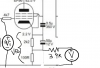
In the stock configuration, the 120k supplies g2 (3) with DC and a small amount of NFB. It also applies PFB to the cathode (6) through a 1uf capacitor. The 1uf capacitors impedance of 8k at 20hz means the NFB to g2 will decrease (to its minimum) with increasing frequency and the amount of PFB to the cathode will increases (to its maximum) with rising frequency.

upload_2022-10-20_19-51-41.png
Some, may argue, that the 1uf value was critically chosen to accomplish this. IMO it was probably an economic compromise by the manufacturer, 1uf was as big as they could or were willing to go ($$). If they could have easily gone higher I bet they would of. A value of 100+uf would eliminate all the RC constant stuff happening right in the middle of the audio range. This falls under the "theories" category, but I try and avoid using capacitors as a resistor in the audio range.


So performing the modification will remove these effects, closely maintain the original operating point, balance of the splitter and adds another NFB source (by connecting the screen grid bypass cap to ground). So PFB is removed and new NFB is added. Less PFB and more NFB sounds like a winning combination for less distortion, but without measuring it is just a guess. A descent sounding guess. :music:

Thanks to everyone for the discussion :beerchug:

Hopefully one day I (or someone) can get some real numbers posted.

 
Now, what happens when feedback voltage Vfb (AC) (at the cathode)>Vinput (g1)?

The AC feedback voltage at the cathode can't be greater than the AC voltage impressed on the grid. If that were the case, the grid would be positive relative to the cathode during the negative half of the cycle.

Jack
 
Correct. Elevating the NFB signal simply elevates the signal required at G1 to produce the NFB signal in the first place, so the G1 signal will always be slightly greater than the NFB signal.

I would also offer some clarity for your comment in post #36, wherein you state: "the 120k supplies g2 (3) with DC and a small amount of NFB. It also applies PFB to the cathode (6) through a 1uf capacitor.". As stated, it implies (or could be interpreted to mean) that traditional AC NFB is being applied to the G2 element.

The source that the 120K resistor is connected to contains both AC and DC components, and both appear at the pentode's G2 terminal. But the NFB actually applied to the G2 element is DC only, with virtually zero influence from the AC element present there: As discussed before, the presence of the screen to cathode bypass cap maintains the potential between the cathode and screen grid, so no AC NFB can be inserted at that node. The AC element at the screen grid is simply coupled to the cathode by way of the screen grid bypass cap to provide the AC PFB desired in the design. So of the AC and DC components provided by the 120K resistor, the DC component powers and represents DC NFB to G2 only, while the AC component provides PFB the cathode only. In this case then, there is no traditional AC NFB being supplied by the 120K resistor.

Dave
 
I was actually about to ask if there was truly any AC feedback at the screen because of the cap but Dave beat me to the question. I had been under the impression that it was done basically as a DC servo sort of thing to make sure all the voltages in that circuit were correct. More current flow through the triode would bump the screen voltage, which increases current in the pentode, which reduces plate voltage at the pentode and thus grid voltage on the triode, which reduces current flow in the triode. If you get all the values right on the initial design it should do a very nice job of self-adjusting to keep the inverter voltages all well balanced.

The 120k to a 1uf does present some extra load for the cathode circuit to work into, so theoretically it could upset the AC balance but 120k ought to be large enough to make that not a serious problem, especially given the relatively low amount of signal required to feed a pair of 6bq5 tubes.
 
Gadget -- Dynaco took care of that by using a 22K plate resistor for the splitter, and a 27K for the cathode leg. 27K//120K = 22.04K.

Dave
 
A quick simulation of the original SCA-35 driver circuit indicates the voltage gain to be about 240 from pentode grid to splitter output. The -3dB point (ahead of the output coupling caps) is about 17 Hz without GNFB. Tell me again why this should be modified?

Jack
 
Also, open loop voltage gain of the modified driver shown in Post #1 is about 83. The -3dB point is about 2.5 Hz.

Jack
 
Back
Top Bottom