• The move to the new server is done. There are some software and database maintenance updates in process. This has us passing the hat around to help out. We appreciate any donations. Seriously, even a dollar helps. The payment page may be found here - https://www.audiokarma.org/support.html

Scott 299B Restore

Dave451

AK Subscriber
Subscriber
Hi, Folks. Working on a 299B obtained from a radio buddy. The amp is in good shape physically, but will need the usual work on couplers, electrolytics, etc. I have discovered that the bias supply needs pretty much a complete rebuild. Almost all of the bias supply resistors are high out of spec, the black axial 10uf 25VDC cap is shot, and one of the two electrolytic cans (100+100+10) is leaking. The other 299B restore forums are a great help here, and I have previously restored another 299B. One question: I want to replace the 4uF 250VDC axial cap in the 60V source supply and I have an 8 uF 450 VDC cap in hand. I know the higher voltage isn't a problem, but will I create issues by doubling the value from 4 to 8? Hate to keep paying freight to Mouser for the odd resistor and capacitor I need now and then!
 
Register to hide this ad
Welcome to AK!

I don't believe doubling that cap will hurt as is low in value and your going a bit higher shouldn't hurt , but help. You can maybe measure against values on the schematic to be sure.
 
That cap is in the bias supply correct? Going to 8uf won't be a problem I find that your bias supply is shot as unusual in that it doesnt really work all that hard. You should probably check all the circuitry associated with the bias supply in case there was a problem that caused it to fail. The leaky cap and over heated resistors doesn't sound normal to me. good luck.
 
Hey, thanks guys. I am new here (love AK!), but have been active on the Fisher board (posting on my Fisher X-200), but more of my work has been on Scotts--299B's (2) and an LK-48B. Anyway, the 4 uF cap is in the 60V B+ source for the screen grids in the AF driver side of the 6BL8's. This supply is at the very end of the B+ supply string and just happens to be located near the bias supply, and it's a low current draw, so I can probably get away with it. I'll check the voltages carefully once I get the new bias bridge rectifier in place. As to the resistors, it's not unusual for the 10 and 18 ohm resistors to be a little high (they were), but I was surprised to see R117 (22K 2W) and R115 (56K 1W) as high as they were, so I'll do some poking around there. The amp came with 6BQ5 tubes in it instead of 7189's, a definite no-no, but I'm not sure that would have contributed. The OPT's check good for DC resistance.
 
Update: I triple-checked all the bias supply connections (lots of components in that small space) and decided to power everything up slowly with my Variac. First, I did the bias supply with no tubes and everything looked correct, but with higher voltage without the 12AX7 filament string. I put them in and all the bias supply voltages were spot on with the new components and filament voltages were close/little low, where I wanted them. -25V source was right on spec. I then put the tubes in and brought the AC up very slowly with the Variac. At about 50%, all voltages were good except the 225V and 170V sources, which were being pulled down very low. Studied the schematic and the only thing I could figure was a bad 20 uF section in the C3 can electrolytic. This could explain why R117 and R115 were fried. I lifted both new replacement resistors and they were right on spec. I already knew at least one of the 25 uF 25VDC sections in C3 was bad from ESR checks, and I was planning to change all the cans (C1, C2, C3) to J/J's. I did this and am ready to recheck the voltages with another slow power up. I'll post some pics shortly.
 
Let's call it an abundance of caution. Still worried about the 225V and 170V source draw down, so will use the variac to take the voltage up in steps. No need for a long power up process, as you say, because we're not reforming the caps. Hope that is it.
 
Let's call it an abundance of caution. Still worried about the 225V and 170V source draw down, so will use the variac to take the voltage up in steps. No need for a long power up process, as you say, because we're not reforming the caps. Hope that is it.

I am the same way. Lack of experience drives me to be extra cautious. Tweaking the old saying "an ounce of caution is worth a pound of frustrations".
 
I am the same way. Lack of experience drives me to be extra cautious. Tweaking the old saying "an ounce of caution is worth a pound of frustrations".
Hi BNR, i like your "Primo Beer" logo!
Back to the low 225 and 170v ... that maybe because the tubes have not reach full operating voltages but if that is not the case, then sometimes the extra resistance in a worn out capacitor will drag down the voltages. This will be shown by the can cap getting warm after just a few minutes of operation. cheers.
 
This was the beer my dad, brothers, etc. grew up on. They stopped production for awhile (I think) then they returned to service. It has been years since I had one, but I recall it was not bad tasting. Back to amps.
 
... The amp came with 6BQ5 tubes in it instead of 7189's, a definite no-no, but I'm not sure that would have contributed. ...

I thought the same, till Dave Gillespie explained that it is quiescent dissipation (taking current as well as voltage into account) that is the important factor. He was commenting on the fact that my 222C also came with 6BQ5s. I'll copy his comment here, because it's really instructive and because the 299B is pretty similar to the 222C.

Dave writes:
If I may -- the reason that the output tubes have lasted so long, is because the LK48/222 series of amplifiers are in fact quite easy on the output tubes.

It is easy to get caught up in voltage concerns -- particularly with 6BQ5 class tubes -- and look a circuit with 400+ volts applied to the plate, and make the conclusion that because of the high voltage, either 6BQ5 tubes absolutely cannot be used, or it is running 7189 tubes right at the limit, and so the unit is very hard on the tubes. But if so, then there's a huge disconnect because in the case of the amplifier at hand -- and the many I have run in to -- the tubes seem to live a very long life indeed. It's not because my own LK48B-C1 came with premium Telefunken power tubes.

Voltage rating is important -- as it relates to catastrophic failures. But even those are published as guidelines. Yet if the appropriate precautions are taken -- which Scott did -- then those voltage ratings can be exceeded (within reason of course) without fear of internal breakdown or failure. Clearly, history shows this to be the case, as this series of amplifiers is not known for the output tubes having fits of melt down if it has been properly maintained.

If fact, over time, given a proper design and typical home use, it is the steady state dissipation level (a product of voltage AND current) that is the primary life determining factor for the output tubes. Type of use can come into play as well if large amounts of power output are expected on a continuous basis. But in a typical home application, by far, it is the steady state dissipation level that is the main determining factor.

Now ALL tubes within the 6BQ5 class of tubes have either a 12 watt plate dissipation rating, or a 13.2 watt rating, depending on whether you're looking at data published under either the older Design Center, or the newer Design Maximum rating systems respectively. 6BQ5, 7189, 7189A, EL84, it doesn't matter. Yet based on the design of the (somewhat goofy) bias adjustment switch of my model, the circuit intends to operate the output tubes at just 20 ma of quiescent current each. If you allow that about 2 ma of this is for screen current, that means that the plate current is only on the order of about 18 ma. At a plate voltage of 420 volts or even more, this represents a plate dissipation of not even 8 watts, or operation at about 60% of the Design Maximum rating for the tube. This is extremely conservative operation.

I'm not sure what the exact bias procedure is for your specific version of this model platform, but in any event, it won't deviate significantly from the overall results described here.

So while voltage rating IS important as it relates to specific circuit design, once that is established however, it is the steady state dissipation level that is the huge life determining factor for the tubes in the design. In at least this example of Scott engineering then, the output tubes should last a very long time indeed!

 
Thanks for the feedback, guys. Primo, I thought about the tubes not being at full voltage/conducting, but my thinking is that that would make the voltage high, not low, since little or no current would be flowing through those circuits. Therefore, focus on the caps. Hey, we'll see. Dandy, thanks much for the quote from Dave G. I pay close attention to whatever he posts and used a lot of his guidance working on my Fisher X-200. The guy I bought the amp from made the same basic observation about the 6BQ5's apparently long life in this particular unit (he's my local guru on tube matters). One thing, though. The 299B spec for each pair of 7189 output tubes is 55 mA of quiescent cathode current. So, that would put each tube at 27.5 mA cathode current; subtracting 3 mA gives 24.5 mA approximate plate current. At 420 V, this would give 10.3 watts idle plate dissipation--about 86% of the 12W max. The spec for the 222C/D/LK-48B is indeed only 44 mA, so I wonder at the difference. The 299B is known as a hot-running amp, but 25% higher idle dissipation is quite a bit hotter! Obviously, it would be good to bias down for the 6BQ5's and I have read that folks bias down the 299B to around 50 mA instead of 55. I wonder what effect running a 299B at 44 mA on each pair would have on the sound/distortion levels? Probably wouldn't be able to notice.

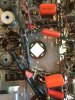
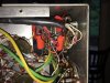
Anyway, here are a couple of pictures of the bias supply work (just before I soldered all the connections). I put in a 2-lug terminal strip so the -25V connections wouldn't be 'in the air' and was able to use 100 uF 100VDC axials underneath the resistor string. The aforementioned 8 uF 450VDC cap is very visible, but it is actually smaller than the original. Had to go above the resistors, though, because of the 100 uF's underneath, but skinny enough to present no clearance problem with the bottom plate. I replaced the 10 ohm dropping resistor with a 30 ohm 3W metal film resistor after installing the new rectifier bridge. Dave
 

Attachments

  • 299BBiasAfter.jpg
    299BBiasAfter.jpg
    77.6 KB · Views: 139
By the way, I noticed that I took this shot just before I installed a replacement for the 22K 2W dropping resistor under the 8 uF cap. It did make it's way in there!
 
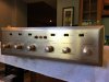
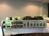
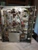
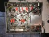
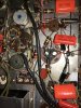
Stepping back into time, though I would include a couple shots of the amp as received. A partial recap had been done on the couplers to the output tubes with 'brown drops.' These are the remaining Cera Caps were replaced with 716 type Orange Drops (see after photo). I did these before the cans (now complete). The amp (particularly the front plate) is in quite good shape and should clean up nicely.
 

Attachments

  • 299BFront.jpg
    299BFront.jpg
    81.5 KB · Views: 141
  • 299BRear.jpg
    299BRear.jpg
    74 KB · Views: 134
  • 299BChassisPre.jpg
    299BChassisPre.jpg
    78.4 KB · Views: 164
  • 299BCoupRecap.jpg
    299BCoupRecap.jpg
    128.6 KB · Views: 171
One other thought. On the 'after coupler recap' shot, you'll see that I left the two 0.0012 uF 400 VDC Pyramid caps in place. These are signal couplers to the first AF amp that, as far as I can tell, receive no DC voltage so I decided to leave them (these were ceramic discs in the other 299B I restored). I'm debating whether to replace the other front end caps, but leaning toward not for the same reason and to keep the front end tone control, etc intact. Any thoughts on this? Leave them or replace them? Thanks. Dave
 
I know that these Ceracaps have a bad reputation, but I agree with leaving in those that don't see high voltage. I replaced those tone caps in my 222C and I think it took away a little of the magic. Not scientific, I know, but still.

Be interesting to hear what current your 299B is biased for now. The Scott site says that they redesigned the output section when moving from 299B to 222C and obviously move from fixed to cathode bias. I wonder how different the OPTs are (TRA-8-4 for 299B and TRA-8-5-1 for 222C)?
 
Last edited:
I had not yet powered it up to check the bias, Dandy, but the good news is that the power up after changing the cans was successful. The voltage draw-down problem on the 225 and 170VDC sources was indeed one or both of the 20 uF sections of C3 can. A little puzzling, since both checked good for ESR but at least one was obviously bad. After powering up carefully, all the B+ voltages in the string were spot on at full line voltage. That explains the high readings in the dropping resistors in that string.

To change the cans, I stole shamelessly from another AK 299B post by GAryB and carefully pulled the cans from the Bakelite bases and epoxied the J/J's onto them. Much better looking to me than clamps (which I have also used). You have to be careful to take all the solder and wire off the tabs and untwist them completely to avoid breaking the wafers when you pull the cans. While the glue set, I cleaned and worked all the front panel pots and switches with DeOxit D5, as well as the chassis mounted bias, AC and DC balance controls. I blew out the excess cleaner with canned air.

I set all the balance pots for about mid-range and, after power up, set the output tube grid bias to -15V for a start. Once I was sure the voltages were stable, I hooked up a speakers and got a good (sweet, actually!) sound check with the 6BQ5's after a little 'grumbling' as the new caps settled in. The speakers, by the way, are vintage Scott S-100's ca. 1969 (restoring them as well).

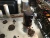
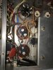
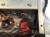
Here are some shots of the cap work. The first shows the C3 base after pulling the old cap. The second and third show the J/J's installed (after using JB Weld expoxy to set them, they're not coming off). The fourth shows the updated wiring around the original 20/20/25/25 uF C3 cap. I put a 2-terminal strip for all the ground connections (shorted), since you don't have all those can tabs available with the new can. The screw head will be under the top cover. I used two Sprague Atom 25 uF 25VDC axials with new, matched 1.5k carbon comp resistors for the V2 and V7 cathodes of the AF amp first stage, These caps are small and fit nicely within the existing wiring. The final shot is of the completed wiring around the HV caps C1 and C2. I drilled out one rivet of the cap base and installed a ground lug since, again, you don't have all the handy lugs with the new cans. The new silicon 400V 3A bias supply bridge is visible, but loose until I pull the power transformer to pull the clip for the old one and screw-mount the new one in the same spot.

During the sound check, I noticed that the pre-amp is quite noisy (hissy and rushy). I plan to change the plate and cathode resistors to deal with this if tube-rolling doesn't solve the problem. Changing the resistors solved the problem with the prior 299B. Comments/questions welcome. Dave
 

Attachments

  • IMG_2146.jpg
    IMG_2146.jpg
    73.8 KB · Views: 122
  • IMG_2167.jpg
    IMG_2167.jpg
    89.2 KB · Views: 119
  • IMG_2173.jpg
    IMG_2173.jpg
    51.3 KB · Views: 117
  • IMG_2160.jpg
    IMG_2160.jpg
    81.4 KB · Views: 127
  • IMG_2166.jpg
    IMG_2166.jpg
    60.5 KB · Views: 125
Thanks. I got this technique from a prior 299B restore thread:

http://audiokarma.org/forums/index.php?threads/hh-scott-type-299.537777/page-2

The topside look is cleaner than using clamps, which is also not a bad way to go having done it before. I've seen some folks who put the clamps below the chassis, but this can be a tight fit with the small underneath space in some amps.

Latest work: I put an Amphenol CL-80 inrush current protector in the AC line. I was able to position it pretty well away from the chassis bottom and other components, particularly the 0.01 disc cap across the a/c line. I pulled the power supply transformer out a ways (being careful not to strain the wires through the chassis grommet), removed the clip for the Siemans selenium bias bridge and used a flat head screw back through to attach the new silicon rectifier bridge( not much space here--a round head screw won't fit) and buttoned it back up.

The phono pre-amp noise issue was tube-related. I had one odd tube, a Holland-made Amperex in the front end 12AX7's (the other three are Telefunken) that was apparently the issue. Traded it with one of the Telefunken and all was well. Need to clean the tube sockets and pins as well.

During this check, though, I got some motor boating with the phono pre-amp engaged, so I decided to change the coupler/signal caps in the pre-amp circuit. These are C12 & 13, C43 & 44, 0.022 and 0.047 uF and are wired directly to the input mode switch, a BEAR to work on. I had to loosen the front end of the chassis (three screws on each side), take the switch (carefully!) out of the front panel, and de-solder a couple of tight wires to get at the switch for the work. My 0.047 orange drops were 600 VDC and almost too big to go in. Note to self: get 400 VDC caps for this next time!

Put it back together and powered up and all is working properly. I am always a little worried about the kind of work like the input switch cap change--it's easy to disrupt things on an old unit like this and I had to work very carefully.
 

Attachments

  • IMG_2180.JPG
    IMG_2180.JPG
    89.6 KB · Views: 82
  • IMG_2188.JPG
    IMG_2188.JPG
    102.2 KB · Views: 80
I did the final two pieces of electrical work on the Scott 299B that I had intended to do. Following the Bill Brittle suggestions from the hhscott.com site, I replaced the four 270K 1/2 W plate resistors in the phono pre-amp state (V1 and V6 12AX7) with precision metal film units and noticed a quite significant decrease in "rush" noise in the "phono" settings. Three of the four original carbon comps had drifted a little high, but not significant. Apparently these do become noise sources over the years though, even if within tolerances for resistance. I've seen this improvement twice when these resistors are replaced, so I believe it.

I checked the plate resistors for the tone control section tubes (100K 1W) and all were well within tolerance (no more that 106K ohms), so I left these be and don't figure them for a noise problem like the phono pre-amp resistors.

He also recommends checking the cathode resistors in the phase inverter/driver circuit. These are 680 and 1500 ohm 10% 1/2 watt units. I checked them and the 680's were right on, but the two 1500's had both drifted a little high (1700-1800 ohms), so I replaced these with matched 1/2 watt 5% carbon comps. All is good on the sound check, so I'm moving on to final cleaning of the chassis and faceplate, then final testing and setup.
 

Attachments

  • IMG_2190.JPG
    IMG_2190.JPG
    121.8 KB · Views: 73
  • IMG_2193.JPG
    IMG_2193.JPG
    102.4 KB · Views: 73
Back
Top Bottom