• The move to the new server is done. There are some software and database maintenance updates in process. This has us passing the hat around to help out. We appreciate any donations. Seriously, even a dollar helps. The payment page may be found here - https://www.audiokarma.org/support.html

Scott LK-72 Rehab

Dave451

AK Subscriber
Subscriber
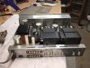
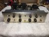
Acquired this a month or two ago and it's been waiting patiently while I completed work on a Sherwood receiver. This kit-built LK-72 7591A amp is a champagne face model with the brown Bakelite knobs, a later model with the DC balance controls, but no way to adjust the overall bias level and output tube cathodes all grounded.

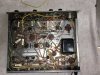
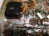
The amp is a bit dusty, but is in excellent shape with only a small nick in the faceplate. Two knobs were missing and replacements were obtained from an AK'er (almost impossible to find?). Inside, it is completely stock with no apparent modifications and no apparent signs of distress. The quality of build looks quite good, with good soldering technique and good lead dress. No leakage from any of the can caps is evident and the original selenium bias/filament rectifier is still present.

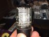
One of the nicest surprises was the tube complement, which consisted of a beautiful Amperex Bugle Boy 5AR4/GZ-34 rectifier (Apparently Mullard Blackburn, by the markings; never actually seen one of these before--see photo), 4 Sylvania 7591A's, two Sylvania 12AX7's in the pre-amp, two Telefunken smooth plate 12AX7's for the tone control amps, and two Tele 6GH8A's for the driver/phase inverters. Even better, all tested good (the output tubes quite good), except for one of the 6GH8A's (shorted/grid emission).

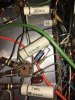
All the original couplers are present, mainly the usual American Radionic Ceracaps.

Initial pre-power checks as follows:
1. Power resistors and 18 ohm resistors in bias circuit all check good, well within specs. The screen resistor R213 is 1200 ohms vs. 750 on the schematic.
2. All electrolytics check good for ESR except the two cathode bias cap sections for the tone control amps V3-A and V4-A. These sections always seem to check bad. I will check all for leakage at max working voltage with my Sprague TO-5 tester.
3. Checked DC resistance of output transformers and power transformers--all good.

I powered it up slowly on the Variac and dim bulb tester with no apparent trouble with the electrolytic caps (all continued cool to the touch after about 4 hours of slowly rising voltage). The selenium rectifier bridge voltage seemed low, so I shut down, pulled the 5AR4 rectifier and went to full AC. Voltage was indeed low at about -39VDC vs. -45 shown on the schematic. I don't want to do any more with all the tubes in until I replace the selenium bridge. The plan is:

1. Replace the selenium bridge with a silicon unit, including upping the first 18 ohm resistor R210 in the bias R-C string (probably with 30 ohm 3 or 4 watt).
2. New couplers across the board (either Orange Drop 716's or Illinois Capacitor polyprop)
3. New 6GH8A to replace the bad driver/phase inverter
4. Check all can electrolytics with the Sprague for leakage current--replace as needed
5. Install new 25 uF 25VDC electrolytics for cathode bypass in the tone control amp
6. Replace 330K grid resistors with 220K
7. Install 100 ohm screen resistors
8. Consider IBAM bias adjustment circuit with 10 ohm cathode resistors.

I'm really looking forward to getting this one going and comparing it to my Fisher X-200 7591A amp and my 7591- and 7868-based receivers (Scott 340B, Fisher 400, Sherwood S9000 IV)!

Dave
 

Attachments

  • IMG_3694.JPG
    IMG_3694.JPG
    120 KB · Views: 263
  • IMG_3695.JPG
    IMG_3695.JPG
    116.6 KB · Views: 245
  • IMG_3696.JPG
    IMG_3696.JPG
    105.3 KB · Views: 248
  • IMG_3697.JPG
    IMG_3697.JPG
    149.1 KB · Views: 273
  • IMG_3702.JPG
    IMG_3702.JPG
    118.2 KB · Views: 254
  • IMG_3703.JPG
    IMG_3703.JPG
    60.2 KB · Views: 241
Register to hide this ad
I was gonna say "you're in for a treat", but then I saw what other great gear you have. Obviously, you've experienced TOTL vintage hi fi.

I installed orange drops for main coupling caps in my LK-72 at first, didn't sound bad at all. Then I switched to Russian K40Y-9....HEAVEN. I highly recommend them.
Was curious how the IC polyprops sounded too.
 
Rather than go IBAM, consider just adding 2 pots for bias, 1 per channel. That will eliminate the need for close matched tubes and is a bit less hassle to get everything biased and balanced. You will have less of the back and forth adjusting that comes with the IBAM. I did it on one I had a few years back and was very happy with the results. Search around for IBBA and you should get more info.
 
Dave -- No reason to change the 330K resistors to 220K, as the Grid #1 DC resistance of this design is well within the specification for the tube. In fact, if you do lower the value of that resistor, you'll upset the bias voltage to the output tubes (unlike with the Fisher designs), so you're fine to leave them as is.

Nice looking Scott!!

Dave
 
Have to agree, add in two bias pots to compliment the existing balance pots and you're golden. If you feel compelled to rework the design so that the pots "fail safe", that wouldn't be a useless thing to do either. Basically duplicate the bias/balance board circuit using the two existing pots plus the two new ones.

personally I like the bias/balance method better anyway. Its less fussy to use overall IMO.
 
Thanks all! I'll go with the two bias adjustment pots as suggested. What value pots did you folks use for the bias level adjustment pots and how did you wire them?

Dave G, thanks much for the reminder--I was just looking reflexively at the 330 K resistors and not the net value of the divider network including the adjustment pots!

JD: I installed IC "yellows" in Fisher 500B and a Fisher 400 receivers and feel they sound at least as good as the 716 series polypropylene Orange Drops. They also have the advantage of smaller physical size (body and leads) and are easier to fit and work with in a crowded chassis. I have not tried the Russian caps, but have read good things about them.

By the way, I replaced the selenium rectifier with silicon today and used a 30 ohm resistor as first in the bias supply R-C string. Bias voltage supply right at -45VDC and now have beautiful sound coming out of both sides of the LK-72! More on that a bit later with a couple of photos…:banana:
Dave
 
Thanks, Patrice. Looks like a good circuit to me and I happen to have two 10 K (as the schematic shows) linear taper trim pots that I can use to set it up. The IBBA and IBAM boards also use 10K trim pots.

So, today's work:
1. Replaced the Siemens selenium bridge rectifier with a 400 PIV 4A unit and replaced R210 (18 ohm, 1 W) with 30 ohm 3 W metal film. This flat, through-hole unit had the pins quite close to the chassis if mounted flat, so I put it on a stand-off through one of the holes left by the clip for the old bridge rectifier. At the rating of this unit, I don't think heat generated will be a problem during operation, though I usually mount the case against the chassis with heat conducting compound.
2. Clipped out the cathode bypass can cap sections (25 uF/25VDC, C14 and C114) for V3-A and V-4A tone control tubes and installed new 25 uF 25 VDC axials with paralleled 1.5k 1/4 watt carbon film resistors directly to pin 8 of these two tubes
3. Replaced the bad 6GH8A driver/phase inverter with a NOS JAN Philips 6U8A obtained from Jim McShane.

Powered back up and checked voltages with AC line about 117 VAC out of the Variac, as follows (measured/schematic): B+ 432/425, 7591A plates 425/420, screens 384/380, grids -17.0 and -17.3 VDC, depending on pair, bias supply -44.9/-45. All looks well in the voltage department. Looks like the tubes will benefit from individual bias adjustment.

Music tested the amp for another hour or so with no apparent heating of the can caps. Output tubes were a nice shade of blue and the sound from my cheap bench speakers was very good. No hum/buzz at all in the line stages at max volume and only a little tube rush from the phono section at max, no hum or buzz there either. The volume control pot is a little scratchy and will be cleaned, along with all the other pots and switches. Getting good balance between the sides.

I'm going to move on with the plan tomorrow, with leakage tests for all remaining can cap sections to see what needs replaced for when I order the couplers and other parts. It's all good so far.
Dave
 

Attachments

  • IMG_3715.JPG
    IMG_3715.JPG
    124.1 KB · Views: 166
  • IMG_3716.JPG
    IMG_3716.JPG
    71 KB · Views: 163
  • IMG_3711.JPG
    IMG_3711.JPG
    17.5 KB · Views: 151
The silicon bridge on mine is mounted the same way and I never feared about the heat. As for the bias circuit, mine is crude meaning there's no electrolytics connected to my two 100k pots. A question, what is the purpose of those lytic caps in the bias circuit?

Looking at the 299D schematic as an example, I don't see any electrolytics tied to the bias pots: http://hhscott.com/pdf/fs/299D_2.JPG
 
Last edited:
isolation between the output tubes. The caps shunt any AC (audio signal) to ground so you don't get any signal going to the wrong grid.
 
The way that one is designed it doesn't need extra caps. Some other bias / balance arrangements do need it in order to not cause troubles though.

The trick is in how you set up the pots. This one relies on the pots working in order to keep the tubes from melting. If the wiper lifts on either pot, you lose the bias feed to the output tubes and they can run away. The ones that are a fail safe arrangement would make the tubes go to full cutoff in the event of a pot failure. This is an example of that

Fisher reciever bias balance schematic.jpg

If not for the caps on this one, you'd have some amount of grid signal from both halves of the inverter meeting. Those particular values probably will not work on a Scott because of the different voltages involved, but the basic circuit design could be applied if you changed the resistor values.

or just use the 299D arrangement and use good quality pots.
 
Last edited:
So, let me rephrase Gadget, do I absolutely need to add them in my LK-72 chocolate brown version (6GH8 phase splitters).

For now, the wiper of my 100k pots goes directly to the balance pot. On one side, they are obviously feed by the negative bias voltage and there are 100 k resistors on the other side to ground.

Thanks,

Patrice
 
nah, you're fine if you have the setup like the 299D schematic linked above.

Actually using that setup, if you put caps in the wrong spot it would make it worse. I don't feel like doing the math right now but it would end up presenting a lower impedance load to the phase inverter and that would likely cause problems.
 
Gadget, how do you like the circuit Patrick posted in posted #8 for the LK-72?
Its almost the same as the 299D circuit. Different value pots but thats not a big matter. Other than some resistor values its functionally identical to what my Pilot SA-260 uses too. Just know that if the pot fails, you lose bias to the tubes so don't use crappy parts.
 
Sorry, Patrice--didn't mean to call you Patrick, just fat-fingered the keyboard. I'll likely stick with the circuit you provided but, Gadget, I was already looking over the same picture of Dave's as well. I put that very unit in my Fisher 400 (along with EFB) and the 500B that I restored and it works very well. The bias supply voltage is -45 for the LK-72 instead of the -25 VDC in the Fishers, so resistance values might need to be changed if I go that way.

JD, yep I asked the question on the lack of a Scott forum as well and haven't really gotten a good answer, other that it was proposed but not done. Surely there's enough going on and interest in Scott gear to justify it?

Anyway, today's work was to un-wire and test all the can electrolytics and, sad to say, none made the grade even though the amp was working fine and they didn't seem to be heating up. I used the Sprague Tel-Ohmike TO-5 tester, which can apply up to 600VDC to an electrolytic and measure pretty precisely the leakage current at max working voltage. One can might have been OK, but the leakage values at max working voltage were enough to worry me about long term viability, so out it goes along with the rest. I also recently had to similarly replace every can in the Sherwood S8000 IV I rehabbed, but prior to these two at least some would pass muster. It's a pretty severe test, though.

The set up of the LK-72 makes replacing the cans easier than some. As per above, I already replaced the 25 uF/25VDC sections in the cathodes of the first tone control amp tube sections. That leaves a 2X30 uF/500 cap (parallel strapped to produce 60 uF), a 2X20 uF/450V and another 2x30 uF/500V. This is pretty straightforward: I ordered three F&T 2X32uF/500V units to replace them. The JJ's would have also worked (also 2x32/500), but I decided I liked blue color cans for this unit instead of black. I'll disconnect the 4X75uF/75VDC bias can and replace with 100 uF/100V axials on a tie strip under the chassis.

The F&T caps don't have mounting tabs, but all the cans on the LK-72 are mounted on phenolic wafers, so I'll carefully remove the old cans and epoxy the new cans to the wafers. I've done this a couple of times and it seems to work well.

I decided to go with Solen 630V Fast Caps for couplers to replace the 0.1 uF units. I already have on hand Solen 0.27 uF to replace the 0.25 uF American Radionics and 716 Orange Drops for the two 0.022 uF caps. I haven't tried Solens in a recap before and am looking forward to hearing what they sound like. I'm not going to change the front panel caps for now.

I was out of 10 ohm and 100 ohm resistors for the 7591A cathodes and screens, respectively, so those are coming. I'm also planning on installing bias test points on top of the chassis and also to place the new bias level pots so the bias/balance adjustment can be done and measured above the chassis.

For the screen resistors, I'm thinking of trying something different than usual. Before, I have installed a couple of tie strips and run a bus for the screen voltage supply, taking the 100 ohm resistors off the bus to the screen pins. On the Sherwood, there was very little room for a bus for the screens, so I used the open pin 8 (7868 tubes) for making interconnections on the screen supply. On 7591's, pin 1 is completely open below the chassis and inside the tube.

QUESTION: can anyone see a reason not to use pin 1 to run jumpers for the screen supply and connect the 100 ohm resistors from pin 1 to pin 8 for screen protection?

As usual, I'll do cleaning of switches, pots, chassis and connectors while waiting for the parts to come in.

Dave
 
Dave -- I routinely run the Screen Stability resistors between pins 1 and 4, with pin 1 acting as the screen grid buss line. You can place the resistors across pins 1 and 8 as well, but either way, you want to leave the jumpers in place between pin 4 and 8.

Dave
 
Back
Top Bottom