

You are using an out of date browser. It may not display this or other websites correctly.
You should upgrade or use an alternative browser.
You should upgrade or use an alternative browser.
Scott LK-72 Rehab
- Thread starter Dave451
- Start date


That particular version of the LK-72 in fact has no bias controls of any type, and will never meet (or even come close to) the manufacturer's power output specification, as that is the version with the TRA-11-1 OPT, which is easily identifiable by the uneven sized end bells. The transformer itself is pretty good as transformers of that type go, but that particular transformer has a 7800Ω primary impedance, that will never let 7591 tubes develop the power that the model was rated for. I'd bet money that this first 72 offering was originally intended to be a cathode biased design. Ergo, the OPTs used, and no bias adjustment facilities. Later versions of the LK-72 used the same transformers as found in the production 299 models (slightly bigger, even end bells, 6500Ω), and started having bias control features, so that there was actually a chance of some correlation between actual performance and specification. The original version of the LK-72 that c_dk is addressing was the subject of my "vintage" Scott restoration thread:
http://audiokarma.org/forums/index....vintage-classic-scotts-original-lk-72.783989/
which was largely made possible because of the oddball transformers employed in the first place.
Dave
http://audiokarma.org/forums/index....vintage-classic-scotts-original-lk-72.783989/
which was largely made possible because of the oddball transformers employed in the first place.
Dave
It has been said that Dave knew more about other rival manufacturers units out in the field than the the rivals in house engineers.......
I wonder if some of the many "updates" that so many of these units seem to have had are a direct response to the dealers holding the manufactures feet to the fire to perform better when faced with such conservative testing......and failing to meet what was advertised.
Ultimately the Federal Trade Commission stepped in to impose the conservative test procedures for amp advertising in I believe 1973.
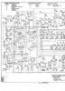
Still have not received the schematic in the mail but have included the photo of it that was sent to me.

I wonder if some of the many "updates" that so many of these units seem to have had are a direct response to the dealers holding the manufactures feet to the fire to perform better when faced with such conservative testing......and failing to meet what was advertised.
Ultimately the Federal Trade Commission stepped in to impose the conservative test procedures for amp advertising in I believe 1973.
Still have not received the schematic in the mail but have included the photo of it that was sent to me.

Dave, it appears that you did a basic replacement of the ceracap capacitors as well as the 4mfd electrolytics.....did you leave the original multicaps.
Does your experience suggest that the modern Tungsol adaption of 7591s would be matched enough in a matched quad to use in the original circuit?
What is the general consensus of the 6U8 to 7199 adapters?
Does your experience suggest that the modern Tungsol adaption of 7591s would be matched enough in a matched quad to use in the original circuit?
What is the general consensus of the 6U8 to 7199 adapters?

I replaced all of the can multi-section caps. I used F&T caps epoxied to the wafers above the chassis and left the bias supply multi in place and replaced it with axials under the chassis. I replaced all the couplers with Solens Fast Caps. My unit did not have the 4 uF capacitors. My experience with the Tung-Sol re-issues is good. In replacing the bias supply bridge rectifier and installing bias adjustment pots I had to move the bias take off up the supply string to get more (negative) bias voltage even for the stock tubes. My current quad of new production Tung Sols are "hot" and my supply won't supply enough bias voltage to get the current down to where I need it, so I stayed with the stock Sylvania's, which were perfectly good.
I installed 10 ohm cathode resistors, bias test points above the chassis, and screen protection resistors as well.
My unit used 6GH8A/6U8A driver/phase inverters, not 7199's. I have heard the adapters are OK to replace 7199's in most applications with 6U8/6GH8 tubes, but some units can have stability problems (most particularly Dynaco). In the Dynaco SCA-35 I rebuilt, there were modifications on the replacement boards to address this. Some of the other folks here may have an opinion on using the adapters in the LK-72--it's probably worth a shot.
My unit had the lower impedance/high output transformers and tested at 35WPC RMS.
I installed 10 ohm cathode resistors, bias test points above the chassis, and screen protection resistors as well.
My unit used 6GH8A/6U8A driver/phase inverters, not 7199's. I have heard the adapters are OK to replace 7199's in most applications with 6U8/6GH8 tubes, but some units can have stability problems (most particularly Dynaco). In the Dynaco SCA-35 I rebuilt, there were modifications on the replacement boards to address this. Some of the other folks here may have an opinion on using the adapters in the LK-72--it's probably worth a shot.
My unit had the lower impedance/high output transformers and tested at 35WPC RMS.
Still have not received the early schematic and build instructions in the mail but I will post the schematic when it arrives.
A few questions come to mind in the mean time...
I would assume the Scott design engineers would have been aware of the tube/transformer primary impedance mismatch......why would they not select a different tube or transformer for the original design.
Was the lack of bias adjustments strictly a cost cutting measure, a simplicity matter for the kit, or not really a big deal because of the quality tube tolerance available back then.
I believe Dave G's EFB boards have been available for various Dynaco units.....is there a generic version available that could be a add on board that would allow individual tube bias?
A few questions come to mind in the mean time...
I would assume the Scott design engineers would have been aware of the tube/transformer primary impedance mismatch......why would they not select a different tube or transformer for the original design.
Was the lack of bias adjustments strictly a cost cutting measure, a simplicity matter for the kit, or not really a big deal because of the quality tube tolerance available back then.
I believe Dave G's EFB boards have been available for various Dynaco units.....is there a generic version available that could be a add on board that would allow individual tube bias?

primosounds
Powered with pure tube sounds.
While, i am not privy to the exact reason why Scott did not make your unit they way they should have. I can imagine a scenario where company profitability at the end of the year, in spite of the engineering department, forsake proper design for saving dollars to bring the equipment cost under the break even point. So it is not far fetched to imagine that they had these transformers available from a previous project or buy out from a transformer company, and wanted to make use of them. And all the other parts necessary to make your unit without dipping into or waiting for other parts to be ordered.I would assume the Scott design engineers would have been aware of the tube/transformer primary impedance mismatch......why would they not select a different tube or transformer for the original design.
Was the lack of bias adjustments strictly a cost cutting measure, a simplicity matter for the kit, or not really a big deal because of the quality tube tolerance available back then.
As to the second question. All of those issues may have played a role in the decision making process. Tubes are very forgiving in requirements and most tube equipment have specs that are around 10% in tolerance. When you work that out , it is a large difference from least to most.
Last edited:
HH Scott was not the only one to monkey around with OPT primary impedance. Fisher -- quite inexplicably -- changed the OPT primary impedance in their 400 receiver from (about) 6500Ω, to nearly double that figure at about 10.5K Ohms. Only the NFB components were changed to accommodate the new turns ratio. On the other hand, if the output tubes were ever overloaded, they quickly became toast with the higher impedance. Of course like Scott, the power output ratings of the 400 were never altered to reflect the lower power output available when the transformer change was made.
Dave
Dave

triode17
Super Member
This looks like the correct sch. It doesn't have any DC balance pots. Also, according to the HH Scott website, the earliest model had the brown faceplate. Mine has the gold faceplate and the Dc bal controls, AKA the LK-72 (A). Personally, I like the sound of my LK-48 better.It has been said that Dave knew more about other rival manufacturers units out in the field than the the rivals in house engineers.......
I wonder if some of the many "updates" that so many of these units seem to have had are a direct response to the dealers holding the manufactures feet to the fire to perform better when faced with such conservative testing......and failing to meet what was advertised.
Ultimately the Federal Trade Commission stepped in to impose the conservative test procedures for amp advertising in I believe 1973.
Still have not received the schematic in the mail but have included the photo of it that was sent to me.
View attachment 1150228
I received the schematic and assembly manuals for the integrated and tuner in yesterday's mail. Will scan and post the schematic today.
Did confirm that this particular version did use a parallel pair of .05 ceramic coupling caps, a interesting design decision for sure and much against both modern and old convention.
Holding the old McClinic graph, seeing my old friends initials and realizing that was his second month of his almost 50 year career with McIntosh brought back lots of fond memories.
As Dave G pointed out in his previous posts, the 7591's misuse in some amps lead to lack of optimum performance and relibility issues. However they seem to work so well in 3 of McIntosh's iconic tube designs: the MAC1500, MA230, and the MC225.
What was Mac engineering doing that the designers at Fisher, Scott, and others not doing?
Did confirm that this particular version did use a parallel pair of .05 ceramic coupling caps, a interesting design decision for sure and much against both modern and old convention.
Holding the old McClinic graph, seeing my old friends initials and realizing that was his second month of his almost 50 year career with McIntosh brought back lots of fond memories.
As Dave G pointed out in his previous posts, the 7591's misuse in some amps lead to lack of optimum performance and relibility issues. However they seem to work so well in 3 of McIntosh's iconic tube designs: the MAC1500, MA230, and the MC225.
What was Mac engineering doing that the designers at Fisher, Scott, and others not doing?
I can't speak for the MAC1500 or the MA230, but in the MC225, the tubes effectively operate into ~ 5200Ω. With the plates and screens operating at the same DC potential from a rather stiff power supply, the screens are safely protected with this load.
Short of Fisher finding a fire sale on transformers -- or possibly in my opinion -- trying to put some distance between the 400 and the 500C and 800C performance wise, it is hard to imaging what engineering concept was behind Fisher's move to such a higher reflected impedance value -- made all the more mysterious by the fact that it appears that only in the 400 was such a move made. Granted, distortion was reduced somewhat with the move, but for what little was gained in that department, it was just a very strange move when viewed on the surface. In Scott's case, I still think the unit originally started life as a cathode biased unit. The lack of chassis controls and transformer primary impedance all support that possibility. The thought is that possibly a change was made at the last moment to compete feature wise with Eico's ST-70 and Fisher's KX-200, which are both fixed bias units, with the competitor's units employing a full set of controls for both Bias and DC Balance, and 6500Ω transformers.
Dave
Short of Fisher finding a fire sale on transformers -- or possibly in my opinion -- trying to put some distance between the 400 and the 500C and 800C performance wise, it is hard to imaging what engineering concept was behind Fisher's move to such a higher reflected impedance value -- made all the more mysterious by the fact that it appears that only in the 400 was such a move made. Granted, distortion was reduced somewhat with the move, but for what little was gained in that department, it was just a very strange move when viewed on the surface. In Scott's case, I still think the unit originally started life as a cathode biased unit. The lack of chassis controls and transformer primary impedance all support that possibility. The thought is that possibly a change was made at the last moment to compete feature wise with Eico's ST-70 and Fisher's KX-200, which are both fixed bias units, with the competitor's units employing a full set of controls for both Bias and DC Balance, and 6500Ω transformers.
Dave
Last edited:


Has anyone got Patrice's post #8 schematic handy? I'd like to get a copy so I can verify stuff on my LK-72.
Thanks
Larry
Thanks
Larry
Larry,
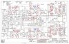
Here's the schematic. It's pretty colorful, but very legible and shows the new bias circuit. I'm also including a shot of my (messy, but identical circuit to the Patrice drawing) diagram in my notes. A couple of notes on implementation:
1. I changed the 10K resistor to 22K between the new 10K linear taper pots and ground. The value of this resistor changes the "spread" of negative bias voltage you get when adjusting the pots and 22K gave me 3 or 3-1/2 V of adjustment from the new pots
2. With the added resistance in the circuit, the bias voltages were a little too hot (not negative enough) to keep the current down on my output tubes (old stock 7591's), so at gadget73's suggestion, I moved the bias take off one step up the R/C string in the 12AX7/bias supply. That is, taking off the bias voltage after R208 instead of R207. Another option is to reduce the value of the first resistor after the bridge rectifier, but this will also raise the filament voltages a little on your front end 12AX7's.
Your mileage may vary depending on your unit, so you might have to fiddle with it a bit.
Dave

Here's the schematic. It's pretty colorful, but very legible and shows the new bias circuit. I'm also including a shot of my (messy, but identical circuit to the Patrice drawing) diagram in my notes. A couple of notes on implementation:
1. I changed the 10K resistor to 22K between the new 10K linear taper pots and ground. The value of this resistor changes the "spread" of negative bias voltage you get when adjusting the pots and 22K gave me 3 or 3-1/2 V of adjustment from the new pots
2. With the added resistance in the circuit, the bias voltages were a little too hot (not negative enough) to keep the current down on my output tubes (old stock 7591's), so at gadget73's suggestion, I moved the bias take off one step up the R/C string in the 12AX7/bias supply. That is, taking off the bias voltage after R208 instead of R207. Another option is to reduce the value of the first resistor after the bridge rectifier, but this will also raise the filament voltages a little on your front end 12AX7's.
Your mileage may vary depending on your unit, so you might have to fiddle with it a bit.
Dave
Attachments
Thanks Dave.
You bet, Larry. One other thing, if you go this way, use good 10K linear pots. If a wiper lifts, it will interrupt the bias to the output tubes with unfortunate results. One advantage of the newer IBAM/IBBA circuits is they are 'fail safe' if you have a pot problem, like a wiper lift. This install is more 'old school' in that regard.
I've had good results with the 10K bournes pots in the IBAM and IBBA boards I've built. I'll end up doing the same here.