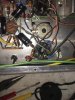
Pretty much completed the electrical rehab work for the LK-72 last 2-3 days after the parts shipment arrived. Completed everything except for a physical cleanup of the chassis, front panel and knobs, including:
1. Cleaned the tube socket pins, pots, rotary and slide switches with DeOxit D5 for the switches and FaderLube for the pots. Also cleaned the RCA connectors and the speaker terminal strips
2. Carefully removed the can caps except for the 4 x 75 uF bias/filament supply filter can. Epoxied three new F&T 2X 32 uF/500 VDC caps to the phenolic wafers that had held the Astron can caps. Wired in the new caps per prior post. One note: you have to be careful when working on this unit to be sure the ground paths are preserved. The ground system is basically a "daisy chain" bus that runs throughout the chassis and is connected to a couple of chassis points. None of the can caps had the can physically soldered to the chassis; all were interconnected with wires forming the ground bus. I was thoughtful about how I did this to avoid introducing ground loops and noise. (photos)
3. Replaced the 4 x 75 uF/75 VDC bias can with four axial IC 100 uF/100V caps. I removed the one point tie strip by the power transformer and installed a new 3 point tie strip with 2 ground points, along with a single on one a transformer screw to accommodate the bias/filament DC supply without any flying leads. All the original 18 ohm resistors from the R-C string tested good, so I reused three of them, along with the 3W 30 ohm metal film resistor I used instead of the fourth 18 ohm 1W right after the rectifier bridge.
4. I installed four red test points near the cathodes of the 7591A output tubes to enable checking the bias above chassis and connected with short wire jumpers. Also mounted a black common negative test point nearby (photos). Because I was going to install 10 ohm cathode resistors, I had removed the 7591 cathode jumpers and, with respect to the ground continuity observation above, installed a ground point under a transformer screw with a star washer, to which I grounded the negative test point, one of the 10 ohm cathode resistors, and the ground point for the 68 ohm resistors in the feedback circuit.
5. Installed 10 ohm 1/2 watt precision metal film resistors on each cathode and grounded each to the nearest ground point.
6. Re-routed the 7591 screen supply to pin 1 of each 7591, removed the inter-tube screen jumpers and left in place the pin 1 to pin 8 screen jumpers on each tube. Installed 100 ohm metal film screen protection resistors between pin 1 and pin 8 on each tube socket. You can see these on the photos.
7. Drilled and mounted two 10K linear taper bias pots between the 12AX7's, basically the only place I could find to mount good-quality pots for top-of-chassis adjustment of bias level. Wired the bias level controls per the schematic provided by Patrice in prior post in this thread with 100 uf 100V electrolytics wired from the new bias control wipers to ground (positive grounded, of course). Cut the bias jumper between the DC balance pots and wired the wipers of the new bias level pots to the wipers of the respective DC balance pots, so now I have a way to adjust both bias level and balance for each side to set a bias level for each tube using the new test points.
8. I replaced all the Ceracap 0.1 uf 400V couplers with Solen Fast Cap 0.1 uF 630V units.
After triple-checking the wiring and new components, I powered up the bias/filament DC supply with only the 12AX7's in place and all checked out well. With a little experimenting, I found that using a 22K resistor in place of the 10K in Patrice's schematic gave me a spread of about 3.5 VDC and I measured from about -18.5VDC to around -15V swing at the tube pins when adjusting the level pot through its full travel.
I put in the rest of the tubes including the 5AR4 rectifier, hooked up speakers and brought power up fairly slowly on the Variac to ease in the new can caps. All was well with B+, plate and screen voltages on the tubes at full line voltage. I have not yet installed a CL-80, as I don't have any on hand, but that will be done before I finish up.
I checked the bias on the tubes and all were fully responsive to the new bias adjustment circuit. Unfortunately, it looks like my original Sylvania 7591A's are getting on--there appears to be one strong tube and one weak in each pair. I was able to balance them fairly closely, but one tube needed around -16.5 volts while the other needed -18.5 volts. At the maximum negative voltage setting on the level pot, the tubes were still drawing around 40-45 mA each and I'm looking for 33 to 35 mA, no more than 38 mA per tube.
I re-balanced the DC balance pots and kept the bias level pots at max negative voltage and tried a new set of Tung-Sol tubes and these were drawing 54 to 56 mA each (!), so I shut them down quickly and put the old ones back in and balanced them for a sound check. The sound was perfectly good with the old tubes and I'm happy to report no buzz or hum, including in the phono mode--just a small amount of tube rush from the phono stage (no ground loops!?).
So, we're in business, but I have to get more negative bias voltage available at the tube pins. Changing out the 'tail' resistor between the bias level pots and ground doesn't do much to increase the overall bias level, it mainly just changes the span of control. After studying, diagramming, and doing calculations on the bias divider network until my head hurt, I'm thinking the only way to raise the overall bias level to the tubes is to change the 270K resistors in the grid circuit to something around 180K and that should do it (get me maybe -20 or -20.5 VDC at max negative). With the bias level pots in the max negative voltage setting, I'm getting the full -45-47VDC to the wipers of the DC balance pots, but still not enough negative bias voltage at the grids to cool down the tubes, apparently.
QUESTION: will changing the resistors in this way result in any stability issues with the 7591 tubes or with the drive level from the driver/PI 6GH8A's (or any other issues)?
So, the pictures show the 'after rehab' state with only a good physical clean up and resolving the bias issue to be complete.
Dave
Pictures: 1) overall underneath after the work, 2) bias/filament supply re-wired with new bridge rectifier, 3) detail of new bias level pots & wiring, 4) Wiring around 7591 tube sockets, including bias test points, 5) Common negative test point and new ground point, 6) Overall view topside, 7) close up of test points, 8) All test points and, 9) new bias level pots, adjustable from above or below deck.