

You are using an out of date browser. It may not display this or other websites correctly.
You should upgrade or use an alternative browser.
You should upgrade or use an alternative browser.
Servicing a SONY DAT machine (Pictorial)
- Thread starter SaSi
- Start date
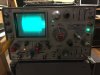
No, this is not good, the left part of the signal is missing (it should be symetrical).
You have probably to raise the left guide (S1) and then adjust the right guide (T1).
The best way to adjust guide is in test mode, after cancelling the auto-tracking (ATF). Look at the service manual.
You have probably to raise the left guide (S1) and then adjust the right guide (T1).
The best way to adjust guide is in test mode, after cancelling the auto-tracking (ATF). Look at the service manual.
Last edited:
Seems strange indeed but I I came to the same conclusion.Question: Why is it that this belt has to be so loose otherwise nothing works?
Check again the tracking (see previous post). It could be the head but the "quality" of the signal seems good.NO: Am struggling to get rid of distortion that I am picking up especially when levels are high. Sounds kind of fuzzy at times? Not sure how to explain but any help from you guys what I can test for to find a fault somewhere perhaps with a scope might sort out this issue please. I have checked the guides alignment and believe I have adjusted them to the best I could with a scope, I have also recapped the RF amp as 4 out of 6 caps had high ESR. What;s causing the distortion during playback? Is it the head that's possibly going faulty? I have tried the mechanism with a different main board (PCM-2300) that I have as spare and ruled out a fault on the board.
The PCM-2700 (or its sibbling DTC-77ES) is indeed a better deck, possibly the best DAT deck ever produced by Sony.2: PCM-2700: I have a working PCM 2700 (thanks to this forum) which I managed to fix after rescuing it from ending up at the dump! Am I right in noticing that it's a superior sounding deck compared to the DTC-750? The transport is so much more reined and quiet when winding a tape however the PCM-2700 refuses to accept any DATA tapes. It won't even wind them.Why is this happening?
Which kind (length) of DDS tape ? There are recognition switches that could prevent to play DDS tapes (lower left of the mecha).
The timer switch connector for timer feature on the 77ES is used for the remote selector on the 2700 so there is a software issue for an easy modification.Can i modify the PCM-2700 to give me the capability of making Timer Recordings? Basically how can I make use of the Remote switching to function as a Timer (Rec/Play) function? In other words how can I convert a pcm2700 to have the timer function of a 77es?
But you can use the D-sub connector on the back (pin 27).

jascha
Active Member
Thank so much once again. I shall have another go trying to realign the guides with the 750. By chance do you conclude that the RF amp is therefore ok?
Regarding the easy modification to manage to have a timer function on the 2700, what do I have to do please? I need some assistance here doing this modification please. What do I do with the sub connector?
In regards to the DSS tapes what do I have to do with the switches please? Or is it the DSS cassette that is different from a DAT cassette and therefore not activating one of the micro switches?
I shall attempt another go at the alignment.
Thanks a lot
Regarding the easy modification to manage to have a timer function on the 2700, what do I have to do please? I need some assistance here doing this modification please. What do I do with the sub connector?
In regards to the DSS tapes what do I have to do with the switches please? Or is it the DSS cassette that is different from a DAT cassette and therefore not activating one of the micro switches?
I shall attempt another go at the alignment.
Thanks a lot
The RF signal looks good so the rf amp should be ok. The scale of the scope is not clear but the level of the center part of the signal should be around 60 mV. BTW I never experienced bad rf amp on the 2700 or other 4 DD decks.
Concerning the timer I believe you should follow the schematic p.11 in the service manual. Use a relay to shorten pin 27 (rec) and pin 1 or 19 or 20 (GND).
Concerning the DDS tapes they have a recognition system called MRS through holes under the tape. Maybe the 2700 is designed to prevent use of DDS. Post a picture of the bottom of your DDS tapes to see if there are holes.
Some information here:
http://www.4crawler.com/Hardware/Tape_Drives/DAT.shtml
Concerning the timer I believe you should follow the schematic p.11 in the service manual. Use a relay to shorten pin 27 (rec) and pin 1 or 19 or 20 (GND).
Concerning the DDS tapes they have a recognition system called MRS through holes under the tape. Maybe the 2700 is designed to prevent use of DDS. Post a picture of the bottom of your DDS tapes to see if there are holes.
Some information here:
http://www.4crawler.com/Hardware/Tape_Drives/DAT.shtml
jascha
Active Member
The RF signal looks good so the rf amp should be ok. The scale of the scope is not clear but the level of the center part of the signal should be around 60 mV. BTW I never experienced bad rf amp on the 2700 or other 4 DD decks.
Concerning the timer I believe you should follow the schematic p.11 in the service manual. Use a relay to shorten pin 27 (rec) and pin 1 or 19 or 20 (GND).
Concerning the DDS tapes they have a recognition system called MRS through holes under the tape. Maybe the 2700 is designed to prevent use of DDS. Post a picture of the bottom of your DDS tapes to see if there are holes.
Some information here:
http://www.4crawler.com/Hardware/Tape_Drives/DAT.shtml
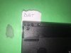
Hi, I took 4 pictures of 4 different kinds including a DAT tape. Dat tape all 3 holes are closed, a DDS2 has hole 1 opened ( counting from left hand edge of cassette), DDS3 has hole 1 and 3 opened and DDS 4 has holes 1 and 2 opened.
I tried to sellotape the holes but still no difference. All I get as a result is the machine going into play mode but as if it's ffwd! No rewind worked. Very strange behaviour.
Attachments


Last edited:
jascha
Active Member
I only have a PDF of the service manual and my page 11 is not a schematic diagram unfortunately. Pin 27 where can I find this please? I am not sure which schematic you refer to. If you can post a picture of the page you refer to that would be fantastic please. Do you therefore mean that if I short pin 27 to ground and switch on the machine it will go into record mode? If so I can perhaps modify the switch that is used as a remote switch? You mention a software modification using the remote connector? Or did I misunderstand? Apologies for all these questions. Cheers
The schematic is on p. 11 labelled 2-12(E). Same page as chapter "3-2 Connection". Shorten the pin 27 and ground available on pins 1/19/20 should put the deck in rec mode.
You can indeed re use the remote switch but need to rewire it to the sub connector on the back plate and rewire the connector on the display board if you still want to use a remote.
No software modification needed. I mentioned it because the timer switch is not implemented in the software. So you have to use a "hard" solution.
You can indeed re use the remote switch but need to rewire it to the sub connector on the back plate and rewire the connector on the display board if you still want to use a remote.
No software modification needed. I mentioned it because the timer switch is not implemented in the software. So you have to use a "hard" solution.
Attachments

jascha
Active Member
Apologies. I did not look properly. I looked at the schematic and only Pin1 and Pin 20 are ground connections according to my schematic. Pin 19 is a +5V out.
I tried shorting pin 27 to pin 1 (no success) and Pin 27 to Pin 20( no success). Should I try Pin 19 as well? I'd rather ask you to double check please.
I tried shorting pin 27 to pin 1 (no success) and Pin 27 to Pin 20( no success). Should I try Pin 19 as well? I'd rather ask you to double check please.
jascha
Active Member
We're getting somewhere but not yet. What I noticed is that the machine will go into Rec mode but in Pause mode. It will only activate the record standby mode that i describe if I short the two pins together AFTER i switch on the machine.
What i am wishing for is that I can set the machine to do Timer recordings in my absence just like a domestic machine. I understand why you mention a relay, which would trigger the short between the two pins (27 and ground) after the machine is turned on. Is there a way to set it to record and play (not pause) with a timer? There must be some way and maybe I did not do exactly what you try to help me?
Any thoughts on the dds tapes and the 2700 (or maybe it's just my 2700?
I will try to adjust the 750 and will update you. Hope it's not the head (how will I find out)?
Cheer hdrobien
What i am wishing for is that I can set the machine to do Timer recordings in my absence just like a domestic machine. I understand why you mention a relay, which would trigger the short between the two pins (27 and ground) after the machine is turned on. Is there a way to set it to record and play (not pause) with a timer? There must be some way and maybe I did not do exactly what you try to help me?
Any thoughts on the dds tapes and the 2700 (or maybe it's just my 2700?
I will try to adjust the 750 and will update you. Hope it's not the head (how will I find out)?
Cheer hdrobien
jascha
Active Member
I believe that you will have to let the 2700 powered on, and use an external timer to shorten pins 27 and ground through a relay.
Concerning the DDS tapes try to fill the holes to fool the deck as I said.
But by shorting the two pins will only put it into record standby, so it still won't record. It did work when I shorted pin 23 to gnd and it put it in play mode, however with record it goes into record and pause. What do you think?
I wonder how the 77es is connected, whether the electronics are similar?
I will try to fool the 2700 with DSS tapes and see if I have any luck
The 77ES is very similar but the connector used for timer is used for the remote selector on the 2700, so the software is slightly different.But by shorting the two pins will only put it into record standby, so it still won't record. It did work when I shorted pin 23 to gnd and it put it in play mode, however with record it goes into record and pause. What do you think?
I wonder how the 77es is connected, whether the electronics are similar?
You can try to shorten with just a pulse, or also shorten the pin 25 (pause).
jascha
Active Member
The 77ES is very similar but the connector used for timer is used for the remote selector on the 2700, so the software is slightly different.
You can try to shorten with just a pulse, or also shorten the pin 25 (pause).
Do you mean shorten pin 27/25/gnd all together?
Question: is the timer connector on the 77es connected to the control board the same way as the remote switch connected to the control board on the 2700? I thought maybe it's a case of reconnecting the connector somewhere else. Can the software be reprogrammed?
jascha
Active Member
DTC-750: I can't seem to get the left part of the signal as you describe (if I am not mistaken). I did readjust the guides and it seems to play fine but will need to listen properly again to make sure. I have set the scope to read 20mv per division and the Time/Div at 1 ms. I shifted the image to be able to get a good image. I did unscrew the left guide and then adjust the right one to have a uniform equal square image. Is it missing something? Thanks for all your help today
Attachments

jascha
Active Member
The 77ES is very similar but the connector used for timer is used for the remote selector on the 2700, so the software is slightly different.
You can try to shorten with just a pulse, or also shorten the pin 25 (pause).
I managed to find out the solution. It works by shorting pin 23(play command) with Pin 27 (Rec command) and ground all together
.Now it's a case of building a relay that shorts all 3 connections a few seconds after the mains timer switches on the DAT machine. Any smart ideas guys?
Something relatively simple please will be great, that could run either from the 240v mains supply or with a transformer, depending on the relay. I have a nice chunky one somewhere and will be happy to put it to use