• The move to the new server is done. There are some software and database maintenance updates in process. This has us passing the hat around to help out. We appreciate any donations. Seriously, even a dollar helps. The payment page may be found here - https://www.audiokarma.org/support.html

Sherwood S-5500 Restorations

rolleiman

Active Member
Hi Team,
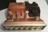
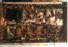
Just purchased a Sherwood S-5500 II (7591 Tubes) and plan to restore it but have been staring at it for a week or two and not quite sure where to begin. What I have done and observed so far:
- I brought the unit up very slowly without the output tubes to ensure electrolytic got conditioned a bit before full power was applied.
Question: is it a bad thing to run amp without output tubes installed. I observed voltages after the input diodes feeding the voltage doubler higher than I expected. 506 volts. Schematic says it should be around 370V. Looks like largest rating on the can cap section is 400 Volts. Explanation?
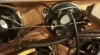
- Power cord is of course old and cracking. I have a bi-polar plug I cut off some newer equipment that has18 gauge wire and says the plug is rated at 7 amps.
Q: is 18 gauge wire sufficient and is there some grommet available to install a new cord appropriately?
Q: can the original plastic grommet be removed without destroying it.
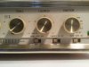
- the black wire of a Green/white and black wire twisted pair coming from one of the channels of the Loudness pot appears to have been cut off and not sure where it needs to be tied to.
Q: thought?

Just beginning the project so much more to follow. Thanks for the help in advance.
 
Register to hide this ad
No output tubes will mean no load on the supply so voltages will be very high. Don't run it at full voltage without the load, the caps will fail.

When you change the caps, its not a terrible idea to bump the voltage. 450v is commonly available, gives it a bit of margin.

Original cord is probably not fatter than 16, and more likely is 18. Its enough. Fuse in these things I think is 2.5 amps?

If you get the proper Heyco pliers, those grommets will come out fairly unscathed. I don't own a set and can confirm channel locks will mangle them.

The black wire is a shield, it should only be grounded at one end. Probably will find that in other spots too.
 
No output tubes will mean no load on the supply so voltages will be very high. Don't run it at full voltage without the load, the caps will fail.

When you change the caps, its not a terrible idea to bump the voltage. 450v is commonly available, gives it a bit of margin.

Original cord is probably not fatter than 16, and more likely is 18. Its enough. Fuse in these things I think is 2.5 amps?

If you get the proper Heyco pliers, those grommets will come out fairly unscathed. I don't own a set and can confirm channel locks will mangle them.

The black wire is a shield, it should only be grounded at one end. Probably will find that in other spots too.

Thanks.
It is interesting that they did ground the other black wire of the twisted pair.
 
I do not have a tool for removing the grommet. Any advise on how to remove and what to replace it with?
 
Be sure to check, re-stuff or replace the multi caps. I just got through doing one of these and it sounds very nice.
 
Be sure to check, re-stuff or replace the multi caps. I just got through doing one of these and it sounds very nice.
Thanks Dave,
Did you remove the cans and re-stuff or install on the bottom? What caps did you end up going with?
 
Fuse says AGC 12 32v and looks pretty heavy duty. Is the a 12amp fuse? Schematic calls for 1-1/2 slow blow. Am I reading the fuse correctly?
 
someone stuck a car fuse in there. Not a good sign. I get very concerned when way too big of a fuse is stuck in things. It tends to turn the transformer into a fuse.

beyond pliers to remove the grommet, don't really have any other suggestion on how to get it out. Fit a new one, they're available. Heyco clamp or grommet is the name of the thing.
 
Another silly question. Does anyone know the appropriate Heyco grommet to order? Noticed that there were several different sizes and do not think they are available locally at a Lowe’s or Ace hardware store.
 
I have a can of various Heyco grommets - measure the hole and I'll send a few. They often can be reused, though.
 
I went with Solen caps, orange drops and Illinois caps. Just sprang for a new multicap can since it was easier from CE. Replaced the output tubes with new set of matched quad Tung-Sol 7591A.
 
I have a can of various Heyco grommets - measure the hole and I'll send a few. They often can be reused, though.
Hi Tom,
The whole is about 12 mm and is D shaped.my new wire insulation is slightly larger than the original so hope it will fit in a new grommet.
Thanks,
Jerry
 
I went with Solen caps, orange drops and Illinois caps. Just sprang for a new multicap can since it was easier from CE. Replaced the output tubes with new set of matched quad Tung-Sol 7591A.
Thank Dave,
Did you have any issues with the multi cap can fitting in your S-5500? The seamed to be slightly too tall.
 
755F4FE8-D96C-4E3F-9C86-26E22D81D073.jpeg Looks like I found an issue with some wiring.
Pins 5, 6 and 7 are shorted on one of the right channel tubes. Wire going to pin 7 is in pretty bad shape.
While I am doing repairs, what else would be recommended. Replace resistors going to pins 6. Replace 470ohm, 7 watt resistor from pin 8? Install bias circuits for each tube?
Thanks
 
2 and 7 are your heater wires. Those should be replaced with a twisted pair like the original was.

6 is the grid. You can change those resistors if you like, but honestly they're not too critical as long as they are somewhere in the ballpark of correct value.

4 and 8 is the screen connection. Its useful to put a 100 ohm resistor between the screen supply and the screen grid to keep things from arcing. I'm not 100% certain here but I *think* you can move the resistor on pin 8 to pin 1, create a new buss to 1 on each tube, and fit a 100 ohm between pin 4/8 and pin 1 to get that done. Pin 1 isn't used for anything and none of the datasheets specifically prohibit use of that pin.

10 ohm resistor between ground and pin 5 is a useful thing for a current monitoring point. 5 probably goes direct to ground now. Goes along well with a bias adjustment, either individual or just a single global control.
 
2 and 7 are your heater wires. Those should be replaced with a twisted pair like the original was.

6 is the grid. You can change those resistors if you like, but honestly they're not too critical as long as they are somewhere in the ballpark of correct value.

4 and 8 is the screen connection. Its useful to put a 100 ohm resistor between the screen supply and the screen grid to keep things from arcing. I'm not 100% certain here but I *think* you can move the resistor on pin 8 to pin 1, create a new buss to 1 on each tube, and fit a 100 ohm between pin 4/8 and pin 1 to get that done. Pin 1 isn't used for anything and none of the datasheets specifically prohibit use of that pin.

10 ohm resistor between ground and pin 5 is a useful thing for a current monitoring point. 5 probably goes direct to ground now. Goes along well with a bias adjustment, either individual or just a single global control.
Thanks, will have to give this some thought as I am no expert in tubes.
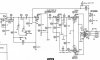
Here is a screenshot of the output section.
F5DBAF6C-84E0-4C86-801B-CC0096D2EE4A.jpeg
 
Back
Top Bottom