

You are using an out of date browser. It may not display this or other websites correctly.
You should upgrade or use an alternative browser.
You should upgrade or use an alternative browser.
Sherwood S-5500 Restorations


rolleiman
Active Member
Any sonic issue with going with a larger value coupling cap, say 0.1uf Or larger as opposed to 0.068 uF? Noticed the mylars that are in there are 600 V parts. Is this overkill or should they really be that high of a voltage?its copper plated steel. for the extremely short lengths involved I can't imagine it making any real difference.
rolleiman
Active Member
Thanks. I did not think about circuit stability. My mind was stuck on capacitive reactance and its effect on the frequency. Ie. Slightly larger cap, lower reactance at a slightly higher frequency. Thanks again, will get 4 matched 0.068uF, 600 v caps.I'd keep the stock values. Sometimes it can mess with stability.
Mine have a mix of 250, 400, and 600v parts. If it has a 600v now it probably needs it.
rolleiman
Active Member
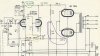
The schematic shows a portion of one of the channels.
- R41 (circled in green) is shown as 82 K. Actual resistor in circuit is 68K, measures 71K.
- Schematic shows R38 and R43 (circled in yellow) in series. Actual circuit has an 820K and 82K in parallel with calculated value of 74.5K ohm and measures 77.1K ohms
- Voltage divider R44 and R45 in circuit are as marked in schematic and measure within 0.24% of each other. The resistors in the other channel for its Voltage divider vary by 4%.
Questions:
1) Why does the schematic value for R41 differ than what is in the circuit? Note, both channels have a 68k ohm in them.
2) in the schematic, what was the intent of using resistor R38 in series with R43 instead of using one resistor? Power dissipation or more control of the resistance by combining resistors to get a closer desired resistance?
3) should the combined resistance of R38 and R42 (in serial or parallel combination) be equal to R41 value?
4) when matching the voltage divider for each output tube, should the 1 K resistors (R55 and R57) be taken into consideration or are the insignificant.
5) Since the resistance of the output divider in the other channel varies by 4% should I replace these with matching resistors?
Thanks

1) running change perhaps. If the schematic has a serial number range that might explain it partly.
2) may have been cheaper to use 2 common values vs buying a less common 75k part.
3) cathode path is R42+R43+R38+(R32+R37 in parallel), or 78k. For equal drive in a typical split load inverter that should match R41. By tying R38 where it is though, its actually getting some positive feedback on the inverter and I'm not entirely sure what that does to the inverter balance. Also possible slightly uneven grid drive gives best performance. Mostly that depends on the specifics of the output transformer. I would honestly be inclined to leave this as-built unless you have some solid reason not to.
4) No reason not to account for them, though its pretty insignificant. Its certainly not going to make it worse if those are closely matched.
5) Also not a major issue, but matching parts side to side is not a bad idea. 4% after a half century is pretty good honestly.
2) may have been cheaper to use 2 common values vs buying a less common 75k part.
3) cathode path is R42+R43+R38+(R32+R37 in parallel), or 78k. For equal drive in a typical split load inverter that should match R41. By tying R38 where it is though, its actually getting some positive feedback on the inverter and I'm not entirely sure what that does to the inverter balance. Also possible slightly uneven grid drive gives best performance. Mostly that depends on the specifics of the output transformer. I would honestly be inclined to leave this as-built unless you have some solid reason not to.
4) No reason not to account for them, though its pretty insignificant. Its certainly not going to make it worse if those are closely matched.
5) Also not a major issue, but matching parts side to side is not a bad idea. 4% after a half century is pretty good honestly.
rolleiman
Active Member
Thank. Appreciate it. My brain is hurting trying to figure out how R32 and R37 are in parallel.1) running change perhaps. If the schematic has a serial number range that might explain it partly.
2) may have been cheaper to use 2 common values vs buying a less common 75k part.
3) cathode path is R42+R43+R38+(R32+R37 in parallel), or 78k. For equal drive in a typical split load inverter that should match R41. By tying R38 where it is though, its actually getting some positive feedback on the inverter and I'm not entirely sure what that does to the inverter balance. Also possible slightly uneven grid drive gives best performance. Mostly that depends on the specifics of the output transformer. I would honestly be inclined to leave this as-built unless you have some solid reason not to.
4) No reason not to account for them, though its pretty insignificant. Its certainly not going to make it worse if those are closely matched.
5) Also not a major issue, but matching parts side to side is not a bad idea. 4% after a half century is pretty good honestly.

R37 goes to ground through the output transformer. R32 just goes to ground. I suppose if you wanted to be extra specific you'd have to add in the fraction of an ohm of DC resistance the output transformer has, but its not significant. Honestly 22k across R32 isn't real significant in DC terms either.
rolleiman
Active Member
Thanks!R37 goes to ground through the output transformer. R32 just goes to ground. I suppose if you wanted to be extra specific you'd have to add in the fraction of an ohm of DC resistance the output transformer has, but its not significant. Honestly 22k across R32 isn't real significant in DC terms either.
See it now.
Guess it is time to order my parts.
rolleiman
Active Member
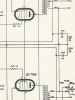
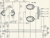
ThanksR+C to ground looks like a Zoebel network. Most likely there for high frequency stability.
The R with parallel C back to the cathode of the 12ax7 is the negative feedback connection. Its there to flatten out frequency response and reduce distortion.
rolleiman
Active Member
There is an indication on the power supply section of the schematic that shows a heater supply for the ECC83 tubes, -24 across two elements. Is this it?The 6.3v supply that makes the tubes light. The output tubes at least run on it, not sure what else does in this one without looking at the schematic.
