• The move to the new server is done. There are some software and database maintenance updates in process. This has us passing the hat around to help out. We appreciate any donations. Seriously, even a dollar helps. The payment page may be found here - https://www.audiokarma.org/support.html

Sherwood S-7900A - Repair and restoration

taligentx

New Member
Hi folks, here's a repair and restoration of a Sherwood S-7900A that initially had no power, and then after swapping a blown fuse would power up but had no sound on any input. It's been an interesting project, hope this helps and feedback appreciated if you see any issues or areas for improvement!

Part 1: Repair

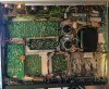
The receiver powered up fine with a new fuse without excessive current draw, as tested with a variac and a dim bulb tester with a 40w bulb. Time to pop the covers - thanks to the designers for making the bottom of the boards easily accessible!
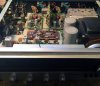
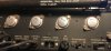
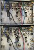
Sherwood S-7900A - 01 - Top.JPG Sherwood S-7900A - 02 - Bottom.JPG Sherwood S-7900A - 03 - Original Outputs.jpg

Starting with the power supply - the power rails measured good, the amp rails are at +/- 44v (spec'd at +/- 43.5v). The low voltage power rails were also good.

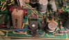
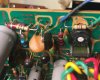
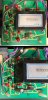
Next was visual inspection - the left amp board seems a bit crispy:
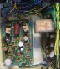
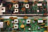
Sherwood S-7900A - 04 - Left Driver.JPG Sherwood S-7900A - 05 - Left Driver Parts.JPG

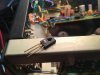
The left channel bias transistor mounted on the heatsink also seems to have a bit of an issue:
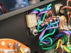
Sherwood S-7900A - 06 - Left Bias Destroyed.JPG Sherwood S-7900A - 07 - Left Bias.JPG

The rest of the boards looked fine visually, so it's time to focus on the left amp board and start testing by pulling component legs:
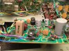
Sherwood S-7900A - 08 - Left Components.JPG

Left amp results:
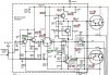
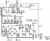
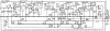
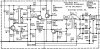
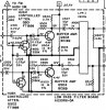
Sherwood S-7900A - 09 - Left Schematic.JPG

Transistors were tested with an AVR transistor tester (though upgraded with precision voltage references and 0.1% reference resistors):
  • Q902 - SPS2196 PNP: Bad, reads as dual diode
  • Q903 - schematic MD8003, actual 2x EN2484 NPN: Both bad, shorted B-C
  • Q904 - schematic SPS2198, actual RCA1A10 PNP: Bad, shorted B-C
  • Q905 - SJE667 NPN: Bad, destroyed
  • Q910 - SJ1902 NPN darlington: Bad, shorted
  • Q911 - SJ1903 PNP darlington: Bad, shorted
  • R911 - 680 ohm: Bad, burned
  • R924 - 120 ohm: Bad, burned
  • R925 - 0.47 ohm: Bad, open
  • R930 - 10 ohm: Bad, burned
  • R935 - 47 ohm: Bad, burned
So the output transistors are shorted (sigh), along with the input differential pair, bias, and one of the driver transistors. Next up, replacing with temporary parts...
 
Last edited:
Register to hide this ad
Nice project. That’s a really fun receiver. Well built and sounds great.
The power transformer size alone is impressive, it's nice seeing a 2-channel 60w/channel receiver with a larger transformer than some 5/7-channel receivers claiming 100w/channel (good luck driving all channels).

The left amp PCB was charred under R935 - this needed to be dug out to avoid any stray conductive paths from the carbon char:
Sherwood S-7900A - 12 - Left PCB.JPG

I didn't keep track of the specific part numbers that I used as temporary replacements - I wasn't too picky (other than verifying voltage ratings) as I would only be testing the amp at a max of 1w, so the parts came from the salvaged parts pile. Rest assured that not a single replacement was on any list of recommended replacements - the joy of using salvaged parts. I did run into an issue with the outputs - I didn't have power Darlington transistors. Avert your eyes if you're sensitive to ugly hacks:
Sherwood S-7900A - 13 - Discrete Darlington.JPG

Voilà, discrete Darlingtons. With the left amp patched up, I checked the protection board for issues (which was visually fine):
Sherwood S-7900A - 10 - Protection.JPG

Protection board results:
Sherwood S-7900A - 11 - Protection Schematic.JPG
  • Q802 - MPS-A70 PNP: Bad, reads as diode only
  • R804 - 240 ohm 5%: Bad, out of tolerance at 191 ohm
One bad transistor in the pair handling the left channel input to the protection board opamp, replaced with a 2N3904/2N3906 pair.

At this point, the receiver was back to having two functional amp channels, but the left channel sounded thin - I initially assumed this was due to its Frankenstein nature, but thanks to a rather convenient front panel control (mono, rev, stereo, left, right), troubleshooting was as simple as setting both amp channels to use the right preamp signal, at which point the left amp sounded fine and matched the right amp. Switched to the left preamp signal and both channels sounded thin. I'm not sure what purpose this control serves in normal usage (as far as being able to select a particular preamp channel) but it was handy for repair.

Next up, troubleshooting the preamp...
 
Good luck with the S-7900A. Owner of an S-8900A and S-7200, epoxied the cracked plastic piece back in place to have the power switch back working in my S-7200.

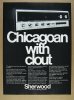
The S-7900A and 8900A were built in Chicago.
Sherwood-S-7900A-Stereo-Receiver-Chicagoan-with-Clout.jpg
 
how is the combo volume/power control pot working?
Good luck with the S-7900A. Owner of an S-8900A and S-7200, epoxied the cracked plastic piece back in place to have the power switch back working in my S-7200.

Hi @59volvo and @dly66 - thanks for the heads-up on the power/volume control pot - it's currently functional but looks like it'll need some attention given that it's such a common failure point.

The S-7900A and 8900A were built in Chicago.

That's a great ad, it's nice to know about the background of this receiver - I'm not familiar with vintage audio so any and all info is appreciated!

Taking a look at the preamp/tone board:
Sherwood S-7900A - 14 - Tone Board.JPG

The bass control pot was measuring odd on the left channel - removed, cleaned, and watched as the left channel track material disintegrated and fell out in pieces as I worked the wiper back and forth. Anyone have a spare or know where to find one? Dual 100k linear taper pot, part# A670R37-0, 1/4” shaft diameter, 5/8” shaft length, 7/16” shaft cutout length, 3/8” bushing diameter, 24mm body diameter, 1/4” bushing thread length:
Sherwood S-7900A - 15 - Bass Pot.JPG

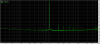
I arbitrarily decided that being able to adjust bass was more useful than treble for now and swapped around the bass/treble pots, then bypassed what is now the bad left channel treble control with a pair of matched resistors for maximally flat response (RMAA measuring at 24-bit/96kHz, left channel/white trace and right channel/green trace):
Sherwood S-7900A - 16 - Frequency Response.JPG

It's not quite ruler flat, there's a -0.4db dip in the midband on both channels but no concern given that this receiver will be driving speakers instead of dummy loads (the sound card itself in loopback is pretty much flat from 100hz to 20khz with a 0.03db drop-off at each end, and -0.25db at 20hz).

One of the dial bulbs was also burned out (#53 BA9S G3-1/2 bulb). With all of the issues identified, troubleshooting is complete - next up, restoration...
 
Part 2: Restoration

The goal of this restoration was to do no harm - there are a few parts that are good candidates for upgrades (like replacing small value electrolytic caps in the signal path with film caps), but otherwise the replacement parts are quite standard.

Power supply:
Sherwood S-7900A - 17 - Power Supply Schematic.JPG
Code:
+------+------------+----------------+-----------------------------+-------------+--------------+
| Part |  Schematic |    Installed   |       Measured Values       | Replacement |    Series    |
|      |    Value   |      Value     +-------------+-------+-------+    Value    |              |
|      |            |                | Capacitance | ESR   | Vloss |             |              |
+------+------------+----------------+-------------+-------+-------+-------------+--------------+
| C184 | 50uF/35v   | 47uF/50v       | 69.47uF     | 0.20Ω | 0.7%  | 47uF/50v    | Panasonic FC |
| C185 |            |                | 65.08uF     | 0.22Ω | 1.4%  |             |              |
+------+------------+----------------+-------------+-------+-------+-------------+              |
| C174 | 220uF/16v  |                | 276.4uF     | 0.10Ω | 2.1%  | 220uF/25v   |              |
+------+------------+----------------+-------------+-------+-------+-------------+              |
| C173 | 220uF/35v  | 220uF/50v      | 295.2uF     | 0.07Ω | 1.1%  | 220uF/63v   |              |
| C175 |            |                | 280.2uF     | 0.07Ω | 1.2%  |             |              |
| C176 |            |                | 274.3uF     | 0.07Ω | 1.0%  |             |              |
| C183 |            |                | 277.2uF     | 0.06Ω | 0.8%  |             |              |
+------+------------+----------------+-------------+-------+-------+-------------+              |
| C172 | 500uF/50v  | 470uF/50v      | 553.2uF     | 0.05Ω | 1.6%  | 470uF/50v   |              |
+------+------------+----------------+-------------+-------+-------+-------------+--------------+
| C183 | 7000uF/50v | 6800uF/63v     | 7997uF      | 0.02Ω | 0.6%  | 6800uF/63v  | Nichicon LLS |
| C186 |            |                | 8140uF      | 0.06Ω | 0.6%  |             |              |
+------+------------+----------------+-------------+-------+-------+-------------+--------------+

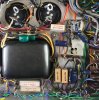
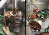
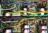
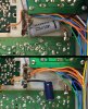
The power supply is wired point-to-point at the bottom of the receiver. All electrolytic caps were replaced, including the main filter caps. The original filter caps measured high on capacity, which may be due to age. Original vs new:
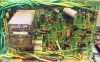
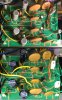
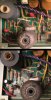
Sherwood S-7900A - 18 - Power Supply.JPG Sherwood S-7900A - 19 - Power Supply Complete.JPG

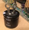
Added crimp eyelets to the replacement filter caps and soldered in place:
Sherwood S-7900A - 20 - Filter Caps.JPG

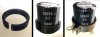
The original filter caps are 40mm diameter, the replacement caps are 35mm and will not fit in the stock clamps. At first, I used thick thermal pads to make up the difference, but didn't like the look of it - the caps tended to end up off-centered in the clamp as the thermal material compressed unequally. A few minutes in Tinkercad and $0.06 worth of PLA filament later:
Sherwood S-7900A - 21 - Clamp Adapter.JPG

This adapter is flexible and compresses with the clamp to give a snug fit for the new caps. I've added this model to Thingiverse for those that have access to a 3D printer: https://www.thingiverse.com/thing:4799918

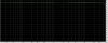
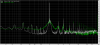
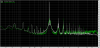
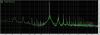
While the ESR and Vloss values indicate that the caps are fine, replacing even just the main filter caps dropped the noise floor nearly 20dB in some places. These measurements are extremely messy (and borderline unusable) thanks to a plasma TV I was using at the time, the only information of value is a general idea of the low frequency noise floor and the very wide skirt of distortion around the 1kHz signal and its harmonics. Replacing the rest of the power supply caps further improved the noise floor and reduced some of the signal distortion:
Sherwood S-7900A - 01 - Right - Power Supply Complete.png

Next up, the preamp/tone board...
 
How does the sound quality of the s-7200 compare to the 7900 and 8900a?
The S-7200 sound I find more appealing. But a bit short of power for the living room setup. The S-8900A has a better tuner in terms of sensitivity and selectivity. I swapped speakers in the living room need to swap the S-8900A back in to see how it does with the current speakers. But then again been liking the sound of the restored old cap coupled Pioneer SX-1500TD in that setup.

On smaller filter caps in brackets I went more low tech and got one of those 2 mm thick foam sheets from Hobby Lobby and cut a strip to wind around capacitor and squeeze it in good.

On my fix and repair S-8900A the relay contacts had turned black letting little signal get through. Fortunately two years ago you could still get the new same model Potter and Brumfield relay, now part of Tyco Electronics, from either Digikey or Mouser for about $20. Then had to track down an intermittent channel drop, ended up being in one of the wires in the tape monitor switch loop. They used solid wire, wire likely was broken at a sharp bend causing the intermittent contact.
 
On my fix and repair S-8900A the relay contacts had turned black letting little signal get through. Fortunately two years ago you could still get the new same model Potter and Brumfield relay, now part of Tyco Electronics, from either Digikey or Mouser for about $20. Then had to track down an intermittent channel drop, ended up being in one of the wires in the tape monitor switch loop. They used solid wire, wire likely was broken at a sharp bend causing the intermittent contact.
Nice catch on the broken wire, that's something I was concerned about, especially when I pulled out the tone board for the bad pot. Also thanks for the heads-up on the relay contacts, they were in decent shape (no oxidation) but did need cleaning to resolve some microphonics - originally when I was testing at high levels into dummy loads, I was able to hear a quiet, very high-pitched version of the source signal coming from the relay. Tip of the day, relays sound terrible as speakers.

Those are some crap transistors you used to replace the old ones. This must be amateur hour!
At least wait until I get the receiver back to you before trolling - next up, how to re-wire a Sherwood to send full voltage rails directly to the speakers if any controls are changed...

Power/volume control pot:
Sherwood S-7900A - 22 - Power Switch.JPG
This is a different design than the Alps power/volume control on other Sherwood receivers seen in this switch repair thread. There's no Alps branding, and the rear wafer isn't held in place by tabs as on the other receivers and would need to be removed by disassembling the back half of the control. The part number and specs are also different:
Code:
+----------+------+------------------------+
| Part #   |   Ω  | Receivers              |
+----------+------+------------------------+
| 28000050 | 100k | S-7100A                |
+----------+------+------------------------+
| 28000051 | 100k | S-7200, S-7210, S-7310 |
+----------+------+------------------------+
| 28000086 | 100k | S-7110                 |
+----------+------+------------------------+
| A671R7-1 |  50k | S-7900A, S-8900A       |
+----------+------+------------------------+
Is this design also affected by the same issue? I only found reports of failure for the Alps 100k control.

Tone board:
Sherwood S-7900A - 23 - Tone Schematic.JPG
Code:
+------+------------+----------------+-----------------------------+-------------+--------------+
| Part |  Schematic |    Installed   |       Measured Values       | Replacement |    Series    |
|      |    Value   |      Value     +-------------+-------+-------+    Value    |              |
|      |            |                | Capacitance | ESR   | Vloss |             |              |
+------+------------+----------------+-------------+-------+-------+-------------+--------------+
| C242 | 10uF/25v   | 10uF/35v       | 11.02uF     | 0.85Ω | 1.2%  | 10uF/50v    | Nichicon UKL |
| C244 | tantalum   | tantalum       | 11.19uF     | 0.52Ω | 1.6%  |             | low leakage  |
| C342 |            |                | 10.91uF     | 3.9Ω  | 0.5%  |             |              |
| C344 |            |                | 9.56uF      | 1.3Ω  | 0.8%  |             |              |
+------+------------+----------------+-------------+-------+-------+             |              |
| C233 | 10uF/35v   |                | 11.75uF     | 0.59Ω | 0.4%  |             |              |
| C241 | tantalum   |                | 12.39uF     | 1.1Ω  | 0.6%  |             |              |
| C333 |            |                | 10.04uF     | 0.67Ω | 0.9%  |             |              |
| C341 |            |                | 12.01uF     | 1.1Ω  | 1.7%  |             |              |
+------+------------+----------------+-------------+-------+-------+-------------+--------------+
C342 has higher ESR than the rest of the tantalums, replacing these helped out the noise floor at the high end:
Sherwood S-7900A - 24 - Tone Board Tantalums.png
Code:
+------+-----------+----------------+-------------+-------------+
| Part | Schematic |    Installed   |   Measured  | Replacement |
|      |    Part   |      Part      |     hFE     |     Part    |
+------+-----------+----------------+-------------+-------------+
| Q203 | S169N     | BC169C         |     544     |   KSC1845   |
| Q303 |           | white dot      |     595     |             |
+------+-----------+----------------+-------------+             |
| Q204 | S169      | BC169C         |     672     |             |
| Q304 |           |                |     325     |             |
+------+-----------+----------------+-------------+-------------+
Q304 has lower gain than the rest of the transistors, these were all replaced with KSC1845's roughly gain matched to within around 0.3%. These are lower gain (ranged from ~355-385) than the BC169C but seem to be functional in this role. This again dropped the noise floor, this time at everything above 300Hz:
Sherwood S-7900A - 25 - Tone Board Transistors.png
Original vs new:
Sherwood S-7900A - 26 - Tone Board.jpg

Next up, the protection board...
 
Last edited:
Could you drop a couple brief words about what you are using to measure distortion? Type of instrument and/or software?

Very enjoyable thread, good pics, documentation, and explanations :thumbsup: ...a breath of fresh air among the same threads/topics that seem to echo around in here, lol.
 
For the bass control you can check on Ebay for needed parts. Either in shipping or sometime between when the auction pictures were taken to when the S-7200 got to me it clearly got dropped and the balance control badly bent. Apparently the balance control pretty much absorbed to hit. Did not take kindly to straightening. Took some time someone parted out an S-7100A that used the same pot and is the one currently in that receiver. The less common the more time it will often take to come up. Then scoring a part at a price deemed acceptable. Some sellers wanted too much for my wallet. I have a few units with donor parts.

I checked the service manual for part numbers to see if the similar vintage S-7100A used the same pot. Since it is a D-shaped shaft you might can find a modern dual gang that would work at Digikey or Mouser. That usually means using to the search filters to narrow the options and then looking at the datasheets for size etc. Might take some other modifications to make it work. Modern choices will likely be much smaller physically.

When I was working on the S-8900A and trying to figure out a potential replacement for the BC169 it looked like the BC550C could work. It is a higher gain transistor than the KSC1845. It looks like the old Seimens BC series ended up with Fairchild who was acquired by On Semiconductor a few years ago. Looking at Mouser it looks like that model is like some other popular vintage transistor replacements and won't potentially be restocked until fall.
 
Could you drop a couple brief words about what you are using to measure distortion? Type of instrument and/or software?

Very enjoyable thread, good pics, documentation, and explanations :thumbsup: ...a breath of fresh air among the same threads/topics that seem to echo around in here, lol.
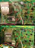
Thank you! This project would not have been possible without the wealth of info that folks have posted here, hope this comes in handy to others.

As far as measurements, the short version is: soundcard + software + resistors.

The long version: Measurements are from RightMark Audio Analyzer (RMAA) - I also like ARTA and Room EQ Wizard (REW), but RMAA is quick and easy for my purposes - grabbing quick measurements before and after making a change to see if there are any obvious differences. If it took more than a minute or two, I probably wouldn't do it. I also have a couple of distortion analyzers (HP 331A and HP 334A), but these take more time to setup and I prefer being able to see the nature of the harmonic distortion rather than just a single THD+N value.

There are issues like the 60hz + harmonics artifacts from AC power (and probable ground loops), and the absolute signal levels are constantly changing (by changing the amp's volume control or adjusting the attenuation from the amp's speaker outputs to the sound card input), hence why I only use this to look for relative differences.

As far as the hardware, I keep an old Macbook around because it has built-in analog + optical digital inputs and outputs - no need for an outboard USB sound card. It uses the Realtek ALC885, which supports 24-bit/192kHz and is spec'd at an SNR of 101dBA on the input - not exceptional but not horrible either. Levels are set with a 1kHz sine wave with the amp volume control set for around 2.83vac RMS on the speaker outputs into 8-ohm power resistors mounted on a heatsink, which are also connected to a linear 1k ohm pot to attenuate the signal before heading to the soundcard input. Testing itself in loopback, THD is at 0.0022% with a noise level at -99dBA:
Macbook - Loopback.png
The higher order harmonics (4th+) are excessive, that's a source issue. One of the projects on the bucket list is to build a low distortion oscillator to make better measurements. The Sherwood is spec'd at 0.1% THD at best with a noise level at -80dB - so for this purpose, this soundcard seems adequate. There's also a lengthy thread on soundcard distortion measurements at diyaudio. Truly a rabbit-hole.

When I was working on the S-8900A and trying to figure out a potential replacement for the BC169 it looked like the BC550C could work. It is a higher gain transistor than the KSC1845. It looks like the old Seimens BC series ended up with Fairchild who was acquired by On Semiconductor a few years ago. Looking at Mouser it looks like that model is like some other popular vintage transistor replacements and won't potentially be restocked until fall.

Agreed, BC550C looks like a good option if the higher gain is critical, unfortunately it's now obsolete. On this S-7900A, Sherwood sometimes mixed BC169B and BC169C, even in identical positions on each channel. I suspect the parts installed may have been selected more for availability rather than gain - it'd be interesting to model the tone board in LTspice but getting into simulation is yet another project on the bucket list.

Protection board:
Sherwood S-7900A - 27 - Protection Schematic.jpg
Code:
+------+------------+----------------+-----------------------------+-------------+--------------+
| Part |  Schematic |    Installed   |       Measured Values       | Replacement |    Series    |
|      |    Value   |      Value     +-------------+-------+-------+    Value    |              |
|      |            |                | Capacitance | ESR   | Vloss |             |              |
+------+------------+----------------+-------------+-------+-------+-------------+--------------+
| C820 | 10uF/10v   | 10uF/35v       | 12.89uF     | 0.78Ω | 0.7%  | 10uF/50v    | Panasonic FC |
+------+------------+----------------+-------------+-------+-------+-------------+--------------+
The single cap on this board measured fine but replaced as a matter of course.
Code:
+------+-----------+----------------+-------------+-------------+
| Part | Schematic |    Installed   |   Measured  | Replacement |
|      |    Part   |      Part      |     hFE     |     Part    |
+------+-----------+----------------+-------------+-------------+
| Q801 | MPS-A20   |                |     293     |   KSC1845   |
| Q803 |           |                |     276     |             |
+------+-----------+----------------+-------------+             |
| Q805 | S169      | BC169C         |     255     |             |
| Q806 |           |                |     547     |             |
+------+-----------+----------------+-------------+-------------+
| Q802 | MPS-A70   |                |    Failed   | KSA992      |
| Q804 |           |                |     96.7    |             |
+------+-----------+----------------+-------------+-------------+
Q802 is bad, Q804 is reading low on gain (should be closer to 200), and Q805 is low on gain. MPS-A20/MPS-A70 have their base as the center pin, 2N3904/2N3906 would be a better fit but I neglected to note the pinout before ordering parts - KSC1845/KSA992 work fine with a bit of leg bending. I considered KSC1815 for Q805 and Q806 as it has higher current handling than KSC1845 but I have more stock of KSC1845.

Also a correction from the repair part - I did swap the opamp (originally RC4558) with a 1458 during troubleshooting. The 4558 wasn't shorted but I had a spare 1458 and didn't feel like chancing it given the extensive damage to the left channel. I had a few other spares like OPA2134 but in this application I went with the more straightforward replacement.

Original vs current:
Sherwood S-7900A - 28 - Protection.jpg

Next up, the phono preamp...
 
Addendum to the protection board - I removed the relay from the board and popped off the cover to clean the contacts, using a strip of paper soaked in acetone followed up by a strip of paper soaked in Deoxit. There was only a bit of contamination, cleaning this mostly resolved the previously mentioned microphonics.

Phono preamp:
Sherwood S-7900A - 29 - Preamp Schematic.jpg
Code:
+------+-----------+----------------+-----------------------------+-------------+--------------+
| Part | Schematic |    Installed   |       Measured Values       | Replacement |    Series    |
|      |   Value   |      Value     +-------------+-------+-------+    Value    |              |
|      |           |                | Capacitance | ESR   | Vloss |             |              |
+------+-----------+----------------+-------------+-------+-------+-------------+--------------+
| C211 | 1uF/35v   | 1uF/50v        | 1.105uF     | 1.9Ω  | 0.7%  | 1uF/63v     | Kemet R82    |
| C311 |           |                | 1.219uF     | 2.3Ω  | 0.6%  |             | film         |
+------+-----------+----------------+-------------+-------+-------+-------------+--------------+
| C200 | 100uF/3v  | 100uF/10v      | 129.5uF     | 0.25Ω | 2.4%  | 100uF/35v   | Nichicon UKL |
| C203 |           |                | 129.0uF     | 0.29Ω | 2.4%  |             | low leakage  |
| C300 |           |                | 128.7uF     | 0.24Ω | 2.8%  |             |              |
| C303 |           |                | 128.7uF     | 0.26Ω | 2.4%  |             |              |
+------+-----------+----------------+-------------+-------+-------+-------------+--------------+
Time for low noise parts - this was an area where I prioritized low leakage over low ESR.
Code:
+------+-----------+----------------+-------------+-------------+
| Part | Schematic |    Installed   |   Measured  | Replacement |
|      |    Part   |      Part      |     hFE     |     Part    |
+------+-----------+----------------+-------------+-------------+
| Q201 |   S169N   |     BC169B     |     300     |   KSC1845   |
| Q301 |           |    white dot   |     302     |             |
| Q302 |           |                |     317     |             |
+------+-----------+----------------+-------------+             |
| Q202 |   S169N   |     BC169C     |     486     |             |
|      |           |    white dot   |             |             |
+------+-----------+----------------+-------------+-------------+
I'm not sure what this is other than a factory production error. Replaced with a set of 4 precision matched KSC1845's (details on this process upcoming).

Original vs current:
Sherwood S-7900A - 29 - Preamp2.jpg

Next up, a few misc parts, then (finally!) the amps...
 
Last edited:
The current versions from On Semiconductor are BC550CBU (bulk) and BC550CTA (tape). Out of stock but not obsolete. Disappointed the KSA1220AYS is soon to be gone.

Looks like you used Kemet R82 film caps.
 
Part 2: Restoration

The goal of this restoration was to do no harm - there are a few parts that are good candidates for upgrades (like replacing small value electrolytic caps in the signal path with film caps), but otherwise the replacement parts are quite standard.

Power supply:
View attachment 2201851
Code:
+------+------------+----------------+-----------------------------+-------------+--------------+
| Part |  Schematic |    Installed   |       Measured Values       | Replacement |    Series    |
|      |    Value   |      Value     +-------------+-------+-------+    Value    |              |
|      |            |                | Capacitance | ESR   | Vloss |             |              |
+------+------------+----------------+-------------+-------+-------+-------------+--------------+
| C184 | 50uF/35v   | 47uF/50v       | 69.47uF     | 0.20Ω | 0.7%  | 47uF/50v    | Panasonic FC |
| C185 |            |                | 65.08uF     | 0.22Ω | 1.4%  |             |              |
+------+------------+----------------+-------------+-------+-------+-------------+              |
| C174 | 220uF/16v  |                | 276.4uF     | 0.10Ω | 2.1%  | 220uF/25v   |              |
+------+------------+----------------+-------------+-------+-------+-------------+              |
| C173 | 220uF/35v  | 220uF/50v      | 295.2uF     | 0.07Ω | 1.1%  | 220uF/63v   |              |
| C175 |            |                | 280.2uF     | 0.07Ω | 1.2%  |             |              |
| C176 |            |                | 274.3uF     | 0.07Ω | 1.0%  |             |              |
| C183 |            |                | 277.2uF     | 0.06Ω | 0.8%  |             |              |
+------+------------+----------------+-------------+-------+-------+-------------+              |
| C172 | 500uF/50v  | 470uF/50v      | 553.2uF     | 0.05Ω | 1.6%  | 470uF/50v   |              |
+------+------------+----------------+-------------+-------+-------+-------------+--------------+
| C183 | 7000uF/50v | 6800uF/63v     | 7997uF      | 0.02Ω | 0.6%  | 6800uF/63v  | Nichicon LLS |
| C186 |            |                | 8140uF      | 0.06Ω | 0.6%  |             |              |
+------+------------+----------------+-------------+-------+-------+-------------+--------------+

The power supply is wired point-to-point at the bottom of the receiver. All electrolytic caps were replaced, including the main filter caps. The original filter caps measured high on capacity, which may be due to age. Original vs new:
View attachment 2201850 View attachment 2202248

Added crimp eyelets to the replacement filter caps and soldered in place:
View attachment 2202253

The original filter caps are 40mm diameter, the replacement caps are 35mm and will not fit in the stock clamps. At first, I used thick thermal pads to make up the difference, but didn't like the look of it - the caps tended to end up off-centered in the clamp as the thermal material compressed unequally. A few minutes in Tinkercad and $0.06 worth of PLA filament later:
View attachment 2202261

This adapter is flexible and compresses with the clamp to give a snug fit for the new caps. I've added this model to Thingiverse for those that have access to a 3D printer: https://www.thingiverse.com/thing:4799918

While the ESR and Vloss values indicate that the caps are fine, replacing even just the main filter caps dropped the noise floor nearly 20dB in some places. These measurements are extremely messy (and borderline unusable) thanks to a plasma TV I was using at the time, the only information of value is a general idea of the low frequency noise floor and the very wide skirt of distortion around the 1kHz signal and its harmonics. Replacing the rest of the power supply caps further improved the noise floor and reduced some of the signal distortion:
View attachment 2202238

Next up, the preamp/tone board...

FWIW, the Illinois capacitors you replaced were probably made at the old IC plant at Clark and Addison, kitty corner from Wrigley Field and only a couple of miles from the California Ave Sherwood plant.

I have a S7900a I was going to restore, but after listening to it I decided to leave it original, other than replacing the burned out dial indicator bulb. I bought the receiver for sentimental reasons- I was born within walking distance of the plant where it was made
 
The current versions from On Semiconductor are BC550CBU (bulk) and BC550CTA (tape). Out of stock but not obsolete. Disappointed the KSA1220AYS is soon to be gone.

Looks like you used Kemet R82 film caps.
Thanks, good to see BC550C is still active, and correct on the Kemet caps. It'll be interesting times if TTC004B/TTCA004B ever go out of production, they're my current replacement for the KSC2690AYS/KSA1220AYS pair. It's also tempting to stock up on KSC3503 for VAS duties.

I originally had no intention of replacing parts on the tuner boards and didn't order parts specifically for them, but I was curious if the electrolytic caps could be replaced without affecting the tuning. From the schematics, it should be fine but there's only one way to find out...

AM IF board:
Sherwood S-7900A - 30 - AM.jpg
Code:
+------+------------+-----------+---------------------------------+-------------+--------------+
| Part |  Schematic | Installed |         Measured Values         | Replacement |    Series    |
|      |    Value   |   Value   +-------------+---------+---------+    Value    |              |
|      |            |           | Capacitance |   ESR   |  Vloss  |             |              |
+------+------------+-----------+-------------+---------+---------+-------------+--------------+
| C411 | 0.22uF/35v |           |   0.232uF   |   17Ω   |   0.1%  |    0.22uF   |   MKT film   |
|      |  tantalum  |           |             |         |         |             |              |
+------+------------+-----------+-------------+---------+---------+-------------+--------------+
| C422 |  4.7uF/25v |           |    6.33uF   |   1.6Ω  |   2.4%  |  4.7uF/50v  | Panasonic FC |
+------+------------+-----------+-------------+---------+---------+-------------+              |
| C402 |  10uF/10v  |  10uF/16v |   12.10uF   |   1.1Ω  |   3.3%  |   10uF/50v  |              |
+------+------------+           +-------------+---------+---------+             |              |
| C419 |  10uF/16v  |           |   11.80uF   |   1.1Ω  |   3.1%  |             |              |
| C420 |            |           |   12.30uF   |  0.91Ω  |   2.1%  |             |              |
+------+------------+-----------+-------------+---------+---------+-------------+              |
| C423 |  33uF/10v  |  33uF/16v |   48.85uF   |  0.46Ω  |   1.7%  |   33uF/50v  |              |
+------+------------+-----------+-------------+---------+---------+-------------+              |
| C415 |  47uF/16v  |           |   67.82uF   |  0.28Ω  |   2.1%  |   47uF/50v  |              |
+------+------------+-----------+-------------+---------+---------+-------------+--------------+
The C411 tantalum's ESR at 17Ω is not a typo, it's the red gumdrop type seen here towards the upper center of the board. Original vs current:
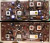
Sherwood S-7900A - 31 - AM Board.jpg

FM RF tuner:
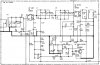
Sherwood S-7900A - 35 - FM RF Schematic.jpg
Code:
+------+-----------+-----------+---------------------------------+-------------+--------------+
| Part | Schematic | Installed |         Measured Values         | Replacement |    Series    |
|      |   Value   |   Value   +-------------+---------+---------+    Value    |              |
|      |           |           | Capacitance |   ESR   |  Vloss  |             |              |
+------+-----------+-----------+-------------+---------+---------+-------------+--------------+
|  C17 | 125uF/16v | 100uF/16v |   119.9uF   |  0.43Ω  |   2.4%  |  100uF/16v  | Panasonic FC |
+------+-----------+-----------+-------------+---------+---------+-------------+--------------+
This is an axial mounted on the bottom of the tuner board to the chassis. Original vs current:
Sherwood S-7900A - 36 - FM RF.jpg

FM IF board:
Sherwood S-7900A - 33 - FM IF Schematic.jpg
Code:
+------+-----------+----------------------+---------------------------------+-------------+--------------+
| Part | Schematic |       Installed      |         Measured Values         | Replacement |    Series    |
|      |   Value   |         Value        +-------------+---------+---------+    Value    |              |
|      |           |                      | Capacitance |   ESR   |  Vloss  |             |              |
+------+-----------+----------------------+-------------+---------+---------+-------------+--------------+
| C102 |  1uF/35v  |        1uF/25v       |    2.15uF   |   7.2Ω  |   3.8%  |   1uF/63v   |   Kemet R82  |
|      |           | Sanyo solid aluminum |             |         |         |             |     film     |
+------+-----------+----------------------+-------------+---------+---------+-------------+--------------+
| C110 |  10uF/35v |       tantalum       |   11.32uF   |   1.7Ω  |   1.2%  |   10uF/50v  | Nichicon UKL |
|      |           |                      |             |         |         |             |  low leakage |
+------+-----------+----------------------+-------------+---------+---------+-------------+--------------+
|  C53 | 220uF/16v |                      |   277.8uF   |  0.11Ω  |   2.3%  |  220uF/25v  | Panasonic FC |
+------+-----------+----------------------+-------------+---------+---------+-------------+--------------+
The Sherwood uses a Sanyo light blue solid aluminum electrolytic cap here as well as at the amp board inputs, these don't age well. Original vs current:
Sherwood S-7900A - 32 - FM IF Board.jpg

FM stereo multiplex:
Sherwood S-7900A - 34 - FM Stereo Schematic.jpg
Code:
+------+-----------+-----------+---------------------------------+-------------+--------------+
| Part | Schematic | Installed |         Measured Values         | Replacement |    Series    |
|      |   Value   |   Value   +-------------+---------+---------+    Value    |              |
|      |           |           | Capacitance |   ESR   |  Vloss  |             |              |
+------+-----------+-----------+-------------+---------+---------+-------------+--------------+
| C130 |  10uF/25v |  10uF/35v |   13.69uF   |  0.44Ω  |   0.9%  |   10uF/50v  | Panasonic FC |
+------+-----------+  tantalum +-------------+---------+---------+             |              |
| C141 |  10uF/35v |           |   12.68uF   |  0.65Ω  |   1.1%  |             |              |
+------+-----------+-----------+-------------+---------+---------+-------------+--------------+
I usually replace tantalums with low leakage types like Nichicon UKL, but Panasonic FC will have to do as I didn't have spare UKLs. Original vs current:
Sherwood S-7900A - 37 - FM Multiplex.jpg

FM lowpass:
Sherwood S-7900A - 38 - FM Lowpass Schematic.jpg
Code:
+------+-----------+-----------+---------------------------------+-------------+--------------+
| Part | Schematic | Installed |         Measured Values         | Replacement |    Series    |
|      |   Value   |   Value   +-------------+---------+---------+    Value    |              |
|      |           |           | Capacitance |   ESR   |  Vloss  |             |              |
+------+-----------+-----------+-------------+---------+---------+-------------+--------------+
| C506 |  10uF/35v |  10uF/16v |   10.71uF   |   1.1Ω  |   0.5%  |   10uF/50v  | Panasonic FC |
| C507 |           |  tantalum |   10.55uF   |  0.45Ω  |   0.5%  |             |              |
+------+-----------+-----------+-------------+---------+---------+-------------+--------------+
This board is left as a future exercise, there are 5x 0.22uF tantalums remaining that can be replaced with film caps. Original vs current:
Sherwood S-7900A - 39 - FM Lowpass.jpg

Verdict: Tuners still work! This should help with reliability, certainly there's no sound quality to be concerned about with radio.
 
FWIW, the Illinois capacitors you replaced were probably made at the old IC plant at Clark and Addison, kitty corner from Wrigley Field and only a couple of miles from the California Ave Sherwood plant.

I have a S7900a I was going to restore, but after listening to it I decided to leave it original, other than replacing the burned out dial indicator bulb. I bought the receiver for sentimental reasons- I was born within walking distance of the plant where it was made
That's great info, thank you - the Illinois caps seem well-made, with only the expected effects of decades of aging (I haven't run across any that were shorted or completely dried out). Sherwood chose well.

Loudness control:
Sherwood S-7900A - 40 - Loudness Schematic.jpg
Code:
+------+------------+------------+---------------------------------+-------------+----------+
| Part |  Schematic |  Installed |         Measured Values         | Replacement |  Series  |
|      |    Value   |    Value   +-------------+---------+---------+    Value    |          |
|      |            |            | Capacitance |   ESR   |  Vloss  |             |          |
+------+------------+------------+-------------+---------+---------+-------------+----------+
| C250 | 0.22uF/25v | 0.22uF/35v |   0.244uF   |   5.1Ω  |   0.6%  |    0.22uF   | MKT film |
| C350 |            |  tantalum  |   0.252uF   |   5.8Ω  |   0.5%  |             |          |
+------+------------+------------+-------------+---------+---------+-------------+----------+
The crusade against tantalums continues. Original vs current:
Sherwood S-7900A - 40 - Loudness.jpg

Also, a clarification - I listed C176 as part of the power supply, it's actually located under the FM multiplex board at the bottom of the receiver:
Sherwood S-7900A - 41 - C176.jpg

Next up, the amps...
 
Back
Top Bottom