• Please note that Audiokarma will be offline briefly for updates early on Monday morning, September 28th.

Sherwood S-7900A - Repair and restoration

I originally had no intention of replacing parts on the tuner boards and didn't order parts specifically for them, but I was curious if the electrolytic caps could be replaced without affecting the tuning. From the schematics, it should be fine but there's only one way to find out...

I have found recapping several vintage receivers replacing the electrolytic capacitors did not adversely affect tuner performance. In some cases sound improved, some caps drift in value or certain types are known to increase ESR as they age.

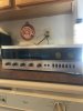
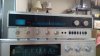
Familiar with the Kemet. My fix and repair S-8900A had not been stored under the best conditions but cleaned up fine (knobs took a bit of polishing). Storage conditions probably the reason the relay contacts had gone black. The way it looked in the Ebay ad probably helped keep its value down.
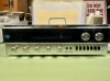
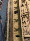
20210425_090046_HDR.jpg ebay front.jpg IMG_20190407_131150.jpg
 
I have found recapping several vintage receivers replacing the electrolytic capacitors did not adversely affect tuner performance. In some cases sound improved, some caps drift in value or certain types are known to increase ESR as they age.

Familiar with the Kemet. My fix and repair S-8900A had not been stored under the best conditions but cleaned up fine (knobs took a bit of polishing). Storage conditions probably the reason the relay contacts had gone black. The way it looked in the Ebay ad probably helped keep its value down.
Good to hear about the tuners on other receivers - and the S-8900A is looking good! Nice to see these being taken care of.

Amplifier boards:
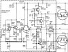
Sherwood S-7900A - 42- Amp Schematic.jpg
Code:
+----------+-----------+----------------------+---------------------------------+-------------+--------------+
|   Part   | Schematic |       Installed      |         Measured Values         | Replacement |    Series    |
|          |   Value   |         Value        +-------------+---------+---------+    Value    |              |
|          |           |                      | Capacitance |   ESR   |  Vloss  |             |              |
+----------+-----------+----------------------+-------------+---------+---------+-------------+--------------+
| C900 (R) |  1uF/35v  |        1uF/25v       |    1.99uF   |   7.9Ω  |   3.8%  |   1uF/63v   |   Kemet R82  |
| C900 (L) |           | Sanyo solid aluminum |    1.79uF   |   9.6Ω  |   3.2%  |             |              |
+----------+-----------+----------------------+-------------+---------+---------+-------------+--------------+
| C910 (R) |  10uF/35v |                      |   12.64uF   |  0.79Ω  |   0.9%  |   10uF/50v  | Nichicon UKL |
| C910 (L) |           |                      |   11.36uF   |  0.84Ω  |   4.3%  |             |              |
+----------+-----------+----------------------+-------------+---------+---------+-------------+              |
| C921 (R) |  47uF/35v |       47uF/50v       |   57.34uF   |  0.21Ω  |   0.7%  |  100uF/35v  |              |
| C921 (L) |           |                      |   58.39uF   |  0.22Ω  |   0.8%  |             |              |
+----------+-----------+----------------------+-------------+---------+---------+-------------+--------------+
| C901 (R) | 220uF/35v |                      |   290.1uF   |  0.06Ω  |   0.8%  |  470uF/50v  | Panasonic FC |
| C901 (L) |           |                      |   283.6uF   |  0.04Ω  |   0.8%  |             |              |
+----------+-----------+----------------------+-------------+---------+---------+-------------+--------------+
This is the other location where Sherwood used the Sanyo light blue solid aluminum electrolytics (C900). These have high ESR (which may be non-linear), but are in series with a 2.2k resistor - I'm curious if the relatively high Vloss would have a more significant impact on the signal than the ESR. Replaced with film caps.

I increased the value of the feedback capacitor (C921) from 47uF to a low leakage 100uF, in theory this may help out with distortion, noise, and DC offset (distortion #8). In practice, there was sufficient room and I had the part available. I also increased the value of the local power supply cap (C901) from 220uF to 470uF.

Looking at the right channel (the channel that did not need repair):
Sherwood S-7900A - 43 - Right Amp Caps.png
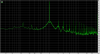
In retrospect, it would have been educational to measure after each capacitor replacement, but I wasn't expecting such a large difference. The noise level at the low end has dropped 10dB (though I must have had the plasma TV on, given the increased high end noise). Most significantly, the wide skirt of distortion around the signal and harmonics is effectively eliminated. Neat!
Code:
+----------+-----------+---------------+---------------+-------------+
|   Part   | Schematic |   Installed   |  Measured hFE | Replacement |
|          |    Part   |      Part     |               |     Part    |
+----------+-----------+---------------+---------------+-------------+
| Q901 (R) |    S169   |     BC169C    |      254      |   KSC1845   |
| Q901 (L) |           |     BC169B    |      242      |             |
+----------+-----------+---------------+---------------+-------------+
| Q902 (R) |  SPS2196  | Motorola 2196 |      541      |    KSA992   |
| Q902 (L) |           |               |     Failed    |             |
+----------+-----------+---------------+---------------+-------------+
| Q903 (R) |   MD8003  |   2x EN2484   |    266/271    |   KSC1845   |
| Q903 (L) |           |               | Failed/Failed |             |
+----------+-----------+---------------+---------------+-------------+
| Q905 (R) |   SJE667  |               |      38.5     |   KSC3503   |
| Q905 (L) |           |               |     Failed    |             |
+----------+-----------+---------------+---------------+-------------+
| Q906 (R) |  SPS2197  |    RCA1A09    |      46.3     |   TTC004B   |
| Q906 (L) |           |               |      39.7     |             |
+----------+-----------+---------------+---------------+-------------+
| Q904 (R) |  SPS2198  |    RCA1A10    |      43.1     |   TTA004B   |
| Q904 (L) |           |               |     Failed    |             |
+----------+-----------+---------------+---------------+-------------+
| Q910 (R) |   SJ1902  |               |      n/a      |   MJ11016G  |
| Q910 (L) |           |               |     Failed    |             |
+----------+-----------+---------------+---------------+-------------+
| Q911 (R) |   SJ1903  |               |      n/a      |   MJ11015G  |
| Q911 (L) |           |               |     Failed    |             |
+----------+-----------+---------------+---------------+-------------+
Q901 is another spot with mixed BC169B/BC169C - though either by design during production or coincidence, the gains are similar. These didn't have a white dot that otherwise (probably) indicates matched devices. Q902 is one of the few PNP small signal transistors in the receiver, replaced with KSA992.

Q905 is the TO-126 bias transistor mounted on the heatsink, replaced with KSC3503. Q904/906 are the TO-39 driver transistors, replaced with TTC004B/TTA004B. I removed the plastic TO-39 mounting spacers and directly installed the replacements.

Typically, KSC2690AYS/KSA1220AYS are the go-to drivers, but as discussed previously, KSA1220AYS is on last shipments/obsolete. Most distributors seem to have final orders placed with ETA's in 5-7 months but the Toshiba pair are still active and this was a good chance to see how they'd work out as replacements.

Q910/Q911 are the TO-3 darlington output transistors mounted outside on the rear of the chassis, under a cover. I used Newark's in-house version of MJ11016G/MJ11015G (120v/200w) as they're both cheaper and (more importantly) in stock. 2N6284/2N6287 (100v/160w) may also be a workable replacement, these are still a bit higher power handling than the original parts (100v/150w).

Next up, the input differential pair (Q903)...
 
Great documentation!

In case your're wondering: Vishay still makes axial elco's. Not cheap and not much of a choice, but proper quality.
 
Amplifier boards, continued...
Sherwood S-7900A - 42- Amp Schematic.jpg
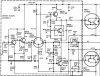
Q903 is the differential pair/long tailed pair that forms the input stage for the amp - the service manual specifies a MD8003, a single package with dual NPNs. This S-7900A uses a pair of discrete EN2484 transistors instead, with similar gain - the right channel pair hFE measured as 266 and 271. An input stage that uses differential pairs is an area that benefits from close component matching, reducing distortion (distortion #1) and DC offset.

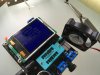
Time to sing the praises of the AVR transistor tester, which (if setup properly per the 140 pages of documentation) works well for troubleshooting and matching components when absolute accuracy and testing conditions are less important than reliably repeatable measurements. I use it for capacitor ESR (the software even has a low voltage in-circuit testing mode), transistors, and low value resistors (0.01Ω resolution for resistors under 10Ω). Currently using the GM328A version (~$12USD shipped), upgraded with a 16MHz crystal, precision voltage references, and 0.1% precision measurement resistors. This EEVblog thread is another rabbit-hole.

Matching transistors:
Sherwood S-7900A - 45 - Transistor Measurement.jpg
Sherwood S-7900A - 44 - Transistor Measurement.jpg
Testing at the same temperature is critical. The added heat from grabbing transistors with fingers is plenty to change the gain, even with the fan it can take 30-40 seconds for the transistor to reach equilibrium for a stable reading. Tweezers are helpful to cut down this time to 5-10 seconds. I sort by measured hFE, and once I have a few matches, re-test them back-to-back to verify (room temperature can change between measurements, etc). This results in transistors that I consider roughly matched.

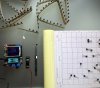
Note that transistors from the same tape reel can have significant differences. I've seen some folks recommending getting cut tape versions and using two transistors next to each other to get a close match, this doesn't work for the KSC1845/KSC1815/KSA992's I've tested. The photo above is of bulk KSA992's, with cut tape KSC1845's at the top waiting for testing. Each batch had the same variance in gain.

For a more precise match, some test setups require perfectly matched components to be able to match transistors. I considered putting together a curve tracer for the oscilloscope as this wouldn't need precision parts, but it looked like a pain to compare readings between more than a couple of transistors. Ideally, there would be something simple that would show the differences between transistors directly, without needing any precision parts...

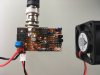
YATMA (Yet Another Transistor MAtcher):
Sherwood S-7900A - 45 - YATMA.jpg
The salvage pile yielded enough parts for YATMA2 - I was short one part for the original YATMA (which of course I found after finishing putting this one together). Note the elegant SMD to DIP conversion.

This works with both oscilloscopes and sound cards, and will show microvolt Vbe differences. After rough sorting by hFE with the AVR transistor tester, it's usually possible to find a closely matched pair out of a group of 3-4 transistors:
Sherwood S-7900A - 46 - YATMA Match.jpg
Each transistor in the pair will bring the signal low, a well matched pair will bring the signal down to the same level - visually, the dips on the scope should have a close bottom level.

Another pair out of the same group of transistors matched by the AVR tester:
Sherwood S-7900A - 47 - YATMA Mismatch.jpg
It's easy to see the mismatch. These are still small differences, just the heat from briefly touching one of the transistors will immediately send the signal off-scale due to thermal differences. The original Sherwood EN2484 pair were also off-scale and not comparable.

For installation, I placed the matched KSC1845's face to face with thermal compound and held in place with heat shrink, with legs arranged to fit:
Sherwood S-7900A - 48 - Q903.JPG

Finally, I matched the R914 and R922 10k resistors by hand from a set of 1% metal film resistors. These affect the input diff pair base currents. The left channel amp had several burned resistors needing replacement, I ended up replacing the resistors on both amps.

Original vs current:
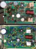
Sherwood S-7900A - 49 - Amp Complete.JPG

The original mica insulators for the output transistors are in good shape, cleaned and applied a small (really, even though the squeeze-out makes it look like it's been slathered on) amount of thermal compound on both surfaces of the insulator:
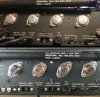
Sherwood S-7900A - 50 - Outputs.JPG

Next up, final adjustments and measurements...

 
Last edited:
Great documentation!

In case your're wondering: Vishay still makes axial elco's. Not cheap and not much of a choice, but proper quality.
Thanks! And yep the Vishay's would be good to maintain the original style, or most of the radials can fit inside the cases of the original Illinois caps if the goal is to keep the original look as much as possible.

Adjustments, measurements, and wrapping up...

The amp board R932 pot is for bias adjustment. The service manual procedure is to look at the nulled output of a distortion analyzer to see when crossover distortion is at a minimum. I took the lazy way out and measured across one of the emitter resistors of each channel (either R925 or R934), adjusting to get 10mV across each resistor. With 0.47 ohm resistors, this is just over 21mA of bias current (further discussion). Adjusting this for minimum crossover distortion is left for a future exercise, but this works as a starting point considering that the Sherwood uses the chassis as a heatsink and increasing the bias will increase the idle temp.

As for DC offset - there's no adjustment pot for this, so the DC offset will be determined by the component tolerances and matching:
Code:
+-----------+--------+--------+
| DC Offset | Before |  After |
+-----------+--------+--------+
| Right     |  -55mV | -2.2mV |
+-----------+--------+--------+
| Left      | Failed | -7.2mV |
+-----------+--------+--------+
It's always nice to see theory work out in reality - matching the input diff pair transistors and feedback resistors brought the DC offset to very low levels.

One last look before getting everything buttoned up:
Sherwood S-7900A - 53 - Left Amp Final.JPG

One of the dial bulbs failed, there are 4x #53 bulbs for the dial and tuning meter. I replaced all of these ($0.09 on clearance at Grainger), but left the stereo bulb as it is a different style. These are easy to replace (especially compared to a Marantz 2230, etc) - just unclip from the back of the dial:
Sherwood S-7900A - 54 - Bulbs.JPG

The dial pointer was off by around 1/4" on FM stations, and was pretty close on AM stations. I briefly considered adjusting the FM tuner itself, then remembered that discretion is the better part of valor. Why, look how easy it is to slip the dial indicator:
Sherwood S-7900A - 55 - Dial Indicator.JPG
How strange, for some reason FM stations are aligned now, but the AM stations seem to be off by 1/4". *ahem*

Finally, the power transformer was buzzing a bit (mechanical 60hz hum), tightening the mounting nuts helped reduce this. It's easier to use a flathead screwdriver just to hold the screws in place, and use a socket wrench from the bottom of the receiver to actually do the tightening. There's still a bit of buzzing when the receiver is initially powered on, but quiets down once it's warmed up. It's a 47 year old transformer in consumer electronics, it gets a pass for not shorting out or overheating after all this time.

All done! Let's see where the parts swapping has taken us...

How it started:
Sherwood S-7900A - 51 - Right THD Original.png

How it's going:
Sherwood S-7900A - 52 - Left THD Final.png

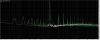
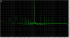
The wide skirts of distortion around the signal + harmonics have been eliminated. The peaks of 60hz + harmonics AC power noise (artifacts from the test setup) are still at the same levels, but the noise floor between the peaks has dropped 20dB. The noise floor actually looks like a floor instead of a rollercoaster!

As far as power, the spec is 60w/channel - the receiver topped out at 76.4w with both channels driven into an 8 ohm dummy load before I visually saw distortion in the output signal on an oscilloscope. It probably was out of spec on THD before this, but the power supply is able to keep up nicely.

A few take-home messages for the S-7900A/S-8900A:
  • Replace all electrolytic capacitors, including the main power supply filters - even if they measure good on capacitance, ESR, and leakage. Yes, the large caps will add $6-$10USD to the parts cost, but as seen here, the main power supply caps measured fine yet replacing them made a significant difference in the noise floor (the main power rails even went up from 44v to 45.3v).
  • The circuit topology doesn't seem sensitive to the original transistor specs, so using low noise parts like KSC1845 works well.
  • Matching the input diff pair transistors and base resistors will help with distortion and DC offset, and even an inexpensive tool like the AVR transistor tester can get closer than the original parts matching.
I know, truly groundbreaking conclusions - but it's nice to see tangible results from the common recommendations. As far as sound, I'm not one for the audiophile superlatives - suffice to say, it sounds good! I can hear a background hiss with an ear right next to the tweeters, but it's inaudible more than a couple of inches away.

Cleaned up and hopefully ready to take on the next few decades:
Sherwood S-7900A - 57 - Chassis.JPG
Sherwood S-7900A - 56 - Front.JPG

-Nikhil
 
Certainly a lot of work both in the unit and write up. Well done.

Considering the series is from 71, with a full complimentary design and Darlington outputs, places this series in a unique position in amplifier history. Also made in USA prior to offshoring production makes these units special.
 
My fix and repair S-8900A had not been stored under the best conditions but cleaned up fine (knobs took a bit of polishing). Storage conditions probably the reason the relay contacts had gone black. The way it looked in the Ebay ad probably helped keep its value down.
@dly66 I'm curious how others have worked on these, which parts did you select for your restoration or which other upgrades/changes did you make? Looks like Elna caps on the driver boards. Also, have you ever measured the DC offset and bias voltage on your S-8900A? It'd be great to compare to other units (especially the bias, I have no idea what the factory setting was on this S-7900A).

Certainly a lot of work both in the unit and write up. Well done.
@Moving Ahead Thank you, and it's been good to see other folks' experiences and feedback.
Considering the series is from 71, with a full complimentary design and Darlington outputs, places this series in a unique position in amplifier history. Also made in USA prior to offshoring production makes these units special.
With the value of vintage Marantz, etc receivers these days, I won't be surprised if the S-7900A/S-8900A shoot up in value for all of the points you mentioned. On top of the sentimental value, they have enough power to drive more modern speakers (that trade efficiency for lower distortion) without clipping as much as the 15-30w receivers.

Here's a parts list for the capacitors (with a few minor updates):
  • Kemet R82 film - DQ/CK/Z3 series have longer lead length
    • 0.22uF/63v - 8x
      • 2x loudness control pot C250, C350 tantalum
      • 1x AM IF board C411 tantalum
      • 5x FM lowpass board C501, C502, C503, C504, C505 tantalum
    • 1uF/63v - 5x
      • 1x FM IF board C102 Sanyo solid aluminum
      • 2x preamp board C211, C311
      • 2x driver board C900 Sanyo solid aluminum
  • Nichicon UKL low leakage
    • 10uF/50v - 15x
      • 1x FM IF board C110 tantalum
      • 2x FM multiplex board C130, C141 tantalum
      • 8x tone board C233, C241, C242, C244, C333, C341, C342, C344 tantalum
      • 2x FM lowpass board C506, C507 tantalum
      • 2x driver board C910
    • 100uF/35v - 6x
      • 4x preamp board C200, C203, C300, C303
      • 2x driver board C921
  • Panasonic FC
    • 4.7uF/50v - 1x AM IF board C422
    • 10uF/50v - 4x
      • 3x AM IF board C402, C419, C420
      • 1x protection board C820
    • 33uF/50v - 1x AM IF board C423
    • 47uF/50v - 3x
      • 2x power supply C184, C185
      • 1x AM IF board C415
    • 100uF/16v - 1x FM RF tuner C17
    • 220uF/35v 4x
      • 1x FM IF board C53
      • 1x power supply C174
      • 2x driver board C901
    • 220uF/63v - 4x power supply C173, C175, C176, C183
    • 470uF/50v - 1x power supply C172
  • Nichicon LLS
    • 6800uF/63v - 2x power supply C183, C186
Transistors (also updated):
  • 2N3904 - 2x protection board MPS-A20 Q801, Q803
  • 2N3906 - 2x protection board MPS-A70 Q802, Q804
  • KSC1815 - 2x protection board BC169C Q805, Q806
  • KSA992 - 2x driver board SPS2196 Q902
  • KSC1845 - 14x
    • 4x preamp board BC169B/C Q201, Q202, Q301, Q302 - matched
    • 4x tone board BC169C Q203, Q204, Q303, Q304 - matched
    • 2x driver board BC169B/C Q901
    • 4x driver board EN2484 Q903 - precision matched
  • TTC004B - 2x driver board RCA1A09 Q906
  • TTA004B - 2x driver board RCA1A10 Q904
  • KSC3503 - 2x amp SJE667 Q905 - mounted on rear chassis
  • MJ11016G - 2x SJ1902 Q910 - mounted on rear chassis
  • MJ11015G - 2x SJ1903 Q911 - mounted on rear chassis
 
On my S-8900A I do believe was the Kemet R82 for the low values, main differences where you likely used the Panasonic FC I used Nichicon UPW and for the filter caps it was CDE, one of the 38?LX series, 50 mm so used the same clamp bent slightly and shifted a screw hole (drilled a hole, let the screw chew the rest. Always double check the R82 datasheet to remind myself of the long lead types, definitely mindful the AA are short leg.

Has most of the original transistors, was not blown up like that one. But have dealt with units where bad things happened in the amp circuit.

The methods Sherwood shows in the service manual for setting bias are not exactly straightforward for what most people would have at home. Trying to remember what I biased it for, will have to check. Did that unit a year or two ago. Will have to double check the DC offsets, I know the S-7200 DC offsets were higher more in the 60-70 mV range. Most service manuals that don't have adjustable offset usually give a spec of more than 200 mV offset as time to look for a bad component.
 
Hi folks, here's a repair and restoration of a Sherwood S-7900A that initially had no power, and then after swapping a blown fuse would power up but had no sound on any input. It's been an interesting project, hope this helps and feedback appreciated if you see any issues or areas for improvement!

Part 1: Repair

The receiver powered up fine with a new fuse without excessive current draw, as tested with a variac and a dim bulb tester with a 40w bulb. Time to pop the covers - thanks to the designers for making the bottom of the boards easily accessible!
View attachment 2201151 View attachment 2201165 View attachment 2201167

Starting with the power supply - the power rails measured good, the amp rails are at +/- 44v (spec'd at +/- 43.5v). The low voltage power rails were also good.

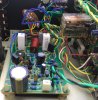
Next was visual inspection - the left amp board seems a bit crispy:
View attachment 2201171 View attachment 2201172

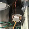
The left channel bias transistor mounted on the heatsink also seems to have a bit of an issue:
View attachment 2201175 View attachment 2201176

The rest of the boards looked fine visually, so it's time to focus on the left amp board and start testing by pulling component legs:
View attachment 2201220

Left amp results:
View attachment 2201268

Transistors were tested with an AVR transistor tester (though upgraded with precision voltage references and 0.1% reference resistors):
  • Q902 - SPS2196 PNP: Bad, reads as dual diode
  • Q903 - schematic MD8003, actual 2x EN2484 NPN: Both bad, shorted B-C
  • Q904 - schematic SPS2198, actual RCA1A10 PNP: Bad, shorted B-C
  • Q905 - SJE667 NPN: Bad, destroyed
  • Q910 - SJ1902 NPN darlington: Bad, shorted
  • Q911 - SJ1903 PNP darlington: Bad, shorted
  • R911 - 680 ohm: Bad, burned
  • R924 - 120 ohm: Bad, burned
  • R925 - 0.47 ohm: Bad, open
  • R930 - 10 ohm: Bad, burned
  • R935 - 47 ohm: Bad, burned
So the output transistors are shorted (sigh), along with the input differential pair, bias, and one of the driver transistors. Next up, replacing with temporary parts...
Hi folks, here's a repair and restoration of a Sherwood S-7900A that initially had no power, and then after swapping a blown fuse would power up but had no sound on any input. It's been an interesting project, hope this helps and feedback appreciated if you see any issues or areas for improvement!

Part 1: Repair

The receiver powered up fine with a new fuse without excessive current draw, as tested with a variac and a dim bulb tester with a 40w bulb. Time to pop the covers - thanks to the designers for making the bottom of the boards easily accessible!
View attachment 2201151 View attachment 2201165 View attachment 2201167

Starting with the power supply - the power rails measured good, the amp rails are at +/- 44v (spec'd at +/- 43.5v). The low voltage power rails were also good.

Next was visual inspection - the left amp board seems a bit crispy:
View attachment 2201171 View attachment 2201172

The left channel bias transistor mounted on the heatsink also seems to have a bit of an issue:
View attachment 2201175 View attachment 2201176

The rest of the boards looked fine visually, so it's time to focus on the left amp board and start testing by pulling component legs:
View attachment 2201220

Left amp results:
View attachment 2201268

Transistors were tested with an AVR transistor tester (though upgraded with precision voltage references and 0.1% reference resistors):
  • Q902 - SPS2196 PNP: Bad, reads as dual diode
  • Q903 - schematic MD8003, actual 2x EN2484 NPN: Both bad, shorted B-C
  • Q904 - schematic SPS2198, actual RCA1A10 PNP: Bad, shorted B-C
  • Q905 - SJE667 NPN: Bad, destroyed
  • Q910 - SJ1902 NPN darlington: Bad, shorted
  • Q911 - SJ1903 PNP darlington: Bad, shorted
  • R911 - 680 ohm: Bad, burned
  • R924 - 120 ohm: Bad, burned
  • R925 - 0.47 ohm: Bad, open
  • R930 - 10 ohm: Bad, burned
  • R935 - 47 ohm: Bad, burned
So the output transistors are shorted (sigh), along with the input differential pair, bias, and one of the driver transistors. Next up, replacing with temporary parts...
 
Interesting, I just stumbled on this restore of your 7900A . I have restored and recapped all on my 8900A a while back which is the same unit with FM only. I have encountered ALOT of similarities with yours - My left channel was out also needed to replace a few transistors on amp driver and outputs too- did not replace any resistors though mine all tested good. Had a similar problem with the bass pot - the bass on the left would not change until bass pot was turned up almost all the way - needed to replace. I replaced transistors on the protection board and when testing the protection the relay did not release- turns out I had either Q805 or 806 in wrong - there the same transistor but 1 needed some leg bending. DC off sets in the end were ~ 1 or 2 mv each channel. In the end this 8900A is one of my BEST vintage receivers - HIGHLY recommended !!! The FM section on this beast beats all my receivers and tuners alike- Iam in a rural area and pick up tons of stations everywhere and sounds great! The amp in here has one of the best soundstages I've heard and highs and mids are spot on and the bass is very strong - punchy - it's non fatiguing. If you can find one get it!! it might need a little work but will be well worth it. I like the the "A" model more the the non "A" . The "A" is a direct connect amp and the non "A" is a cap coupled amp. The non "A" is still a fantastic receiver too don't get me wrong I just give the edge to the "A" model.
 
Hi...I was wondering, who is the Sherwood Tech guru on this sight??? Thanks for your time
There are a lot of people on the forum who have done restoration on Sherwoods, but I don’t think we have anyone who will proclaim themselves as experts. Look at the Sherwood threads where people are looking for technical help with Sherwoods and a few names will stand out.

The problem with Sherwood is that just about every model they made during the classic American period has undocumented changes to the circuit or component values. This makes it a fun brand for people to specialize in. The other issue is that few people collect Sherwood and the value is low compared with other brands. I have 3 receivers (a Kenwood, Pioneer, and Marantz) that I could resell for more money than my entire Sherwood collection combined. (If I leave out the tube gear)
Saying you’re a Sherwood specialist just doesn’t have the same marketing power as saying you’re a McIntosh, Marantz, Pioneer, Kenwood etc specialist. All those brands sell for more money when talking like to like specifications.
 
Yeppers...I have a 2275, a KR10000III, and a pioneer sx950, and the Sherwood kills them all in sound...I'll for sure pay the lower price for way better quality in sound and all...just thought that maybe a Catrafter type person was out there for Sherwood.
 
I have a pretty S-8900A that is quite noisy. I’d love to find a tech to restore it.IMG_0021.jpeg
 
I'm doing an S-8900A and a S-7310A currently. I won't profess to be an expert, just a collector with electronics technician experience.
The S-7310A arrived with severe hum and motor-boating. Fixed that problem by replacing 1 crispy 3.9 k ohm power supply resistor.
The 8900A arrived sounding terrible-I've brought it back to good health. I will need a new Treble pot, as part of the carbon dissolved during D5 cleaning.
Going through both of them in restoration mode.

I bought the latest 2 because I needed a couple more receivers for my shop. The fact they they didn't cost 'stupid money' was a plus! I'm the original owner of an S-7210A since 1979, and the second owner of my brother's S-7250CP (he bought it new in '77). I've always found the sound superior to the 'popular brands'. Besides, I'm more of an Oldsmobile/Pontiac man, instead of the Chevy/Ford world most live in.

As far as running changes in their products, Sherwood DID document them, one just needs the proper service manual replete with updates. They can be hard to find.

I can try to be of assistance in the Sherwood world.
 
Last edited:
Thank you for this thread! I have an S-7100A that I recapped and sounds very nice. I just picked up an S-7900A to hear a Sherwood with a bit more wattage. It sounded good with a quick listen at the sellers location. I opened it up at home as I needed to replace a bulb. After a brief power on (with dim bulb) there was a small trail of smoke and I noticed quite a bit of charring on the right driver board around R910 and R930. Also a small bit of charring up at R938. It appears that this has also added some charring to the solder side of the protection board. The rail voltages measure fine. Then I discovered full rail (43VDC) at the right speaker output. I can't believe the seller didn't fry a driver. Glad I learned (the hard way) to check DC before attaching speakers.
I'm not quite sure where to start troubleshooting without just shotgunning the entire board, so am open to suggestions. I guess pull and check the long tail pair (Q903) and driver transistors. I'm assuming the outputs are good as I heard left and right distinctly at the brief demo. Next time I'll let a unit warm up and do a smell test before purchasing :)
 
I'd check the outputs in the charred (right?) channel. They might have let go.
 
Thank you. I pulled and checked...they're good. I'm just a drummer :).

I'd print out the schematic in post #22 above and start measuring voltages. Use a DBT. The voltages will be slightly lower than the schematic but they should be similar.

you can always post your findings.

R910 should be 24v on one side and V+ on the other side.
R930 should be 43.5v on one side and V+ on the other side.

I always check areas where char'd board/components are. Q901, Q902 might be suspects.

I don't have one but fixed one for a family member. it was in a woodshop and didn't want him to turn it on without some cleaning. I may not be the best to help but post your findings and your next steps. if you were closer, swing by. we can fix it.

1698200215013.jpeg
 
Last edited:
Back
Top Bottom