• The move to the new server is done. There are some software and database maintenance updates in process. This has us passing the hat around to help out. We appreciate any donations. Seriously, even a dollar helps. The payment page may be found here - https://www.audiokarma.org/support.html

Sony CX-0461 solution

lebrun53

New Member
When a TA-1150 Sony integrated amp was brought to my bench with a dead phono circuit,
I needed to find a solution to the unobtanium CX-0461 chip.

Here is what worked for me.
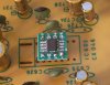
Remove the bad CX-0461 and install a 14 pin DIP socket.
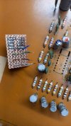
Build a small daughter board with pins long enough to clear the tallest cap under the board (5/8" to 3/4").
I used 2x OPA604 op-amps as replacements.
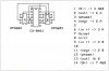
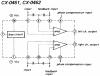
CX-0461-OPA604.jpg
CX0461-1.jpg
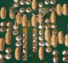
CX0461-2.jpg
notes:
OPA604 is a single op-amp but,
OPA2604 (dual OPA604) could be an option too if you can find them. (no longer available at Digi-Key)
The height off the socket could possibly introduce some interference,
but with the cover installed on the TA-1150, I heard none.

Not shown in the pcb drawing is a .1uF film cap across pins 1 and 14.

The CX-0461 is also used in Sony's STR-7055 and STR-7065 units.
I did not try this solution in either of those other Sony units but I expect it would work there as well.

The CX-0462 chip is very close to the CX-0461 and I think this design would work there as well (not tested).
Larry

--- usual disclaimer - no promises that this will work in your application ---
 
Last edited:
Register to hide this ad
I needed one for my 7065. Took me a year and a half to find it, but i did. Some units had 2. One in phono section, and one in the tone preamp (flat amp). Used mine without a phono for a year and a half. It's whole now.
 
I may have an STC-7k coming my way with a borked CX-0462. I am going to replace it with an NE5532. I have them in SOIC, and then use a SOIC->DIP adapter (Mr. Jack Ma of Aliexpress fame) to connect to the board. The four capacitors across the inputs have to go because the NE5532 doesn't like them. The pinout is almost identical except for the V(-) terminal which has to go from pin#4 to pin#1 (board). Once I have the preceiver working again I will report back here. The supply voltage is high-ish at +/- 19 V but the NE5532 can handle that (max 22 V).
 

Attachments

  • CX0462.png
    CX0462.png
    282.4 KB · Views: 230
  • cx0462_ne5532.jpg
    cx0462_ne5532.jpg
    31 KB · Views: 244
That was a weird fault. Due to a problem in its bias circuit (or something like that) both outputs of the tone amp IC602 would swing almost rail to rail in a 1 Hz rhythm. Replaced it with an NE5532 and it now performs flawless again:

IC602_top.jpg

IC602_bot.jpg

From the two input capacitors one goes to ground and the other one is left floating so the fix can be reversed.
 
Hello,
Old thread I know, but I'm a brand new member and am pretty novice to solid state gear. lebrun53's cx-0461 solution may well solve my problem too, but being new to this I need to know what the pin numbers are on the pcb drawing. Even a verbal description of where pin 1 is on the old and new chips would put me on the right track.
Also, regarding the .1uf film cap across pins 1 and 14- is that a cap already on the Sony board, or an entirely new cap that was added as part of the solution?
And lastly, those two single inline 7 pin connectors used on the breadboard for the solution- are those things that can be purchased from electronics suppliers, and if so what are they called?
Thanks very much for the help!
 
Someone on Ebay had NOS chips a monht ago. Doubt they are counterfit as that is a real obscure chip
 
I may have an STC-7k coming my way with a borked CX-0462. I am going to replace it with an NE5532. I have them in SOIC, and then use a SOIC->DIP adapter (Mr. Jack Ma of Aliexpress fame) to connect to the board. The four capacitors across the inputs have to go because the NE5532 doesn't like them. The pinout is almost identical except for the V(-) terminal which has to go from pin#4 to pin#1 (board). Once I have the preceiver working again I will report back here. The supply voltage is high-ish at +/- 19 V but the NE5532 can handle that (max 22 V).
 
Hello PE9ZZ. I want to thank you for the information. I am working on a Sony STC-7000 where the left channel is barely there and the right channel cuts in and out with a lot of popping.
I did your modification and it works great! I didn't remove any capacitors. The IC was IC603 on the filter amp board. Thanks again. Tom
 
Hi !

Currently on the workbench: A Sony STC-7000 Preceiver and a TA-3200F Final Amplifier.
Both in the same hands for almost 30 years - but no longer used for more than 10 years. They needed a refreshment.

Today I'd intended to put them on the testbed along with a pair of H&H Scott S-15s.
The amp already worked fine on the workbench with two JBLs - but the Preceiver now caused problems.
Apart from the disfunctional FM-Muting all of the sudden the left channel quit with crumbling noises on FM. Mooo !
Turns out: it is the dreaded CX-0462 again. Was guessing about a standard Op-Amp substituion already but found the very same problem and a solution in here.
That's why you have me on your doorsteps now. Found some NE5532 in my stash, but could not build "the patch" due to time contraints (usual excuse - I know).

Will report back what was the outcome.

The 7000 also "features" a similarly dreaded CX-0461 on the phono input board.
What's the opinion on replacing that with a patch as well before trouble arises on the long run ?


:)
 
The 7000 also "features" a similarly dreaded CX-0461 on the phono input board.
What's the opinion on replacing that with a patch as well before trouble arises on the long run?
Toss it. The NE5532 is a great opamp.
 
Hi !
Toss it. The NE5532 is a great opamp.

I'm on the way.
Just returned to the workshop a few minutes ago from my daily tour which went surprisingly well - even though covered 370 km - but no major issues at work or in traffic.
Solderers are warming um, parts prepared, fingers stretched ... Let's go !

:D
 
So now ...

... I would judge that as a success. Both channels on FM returned to normal operation.

CX0462-NE5532_conversion.jpg

That "Patch" might not be the best in the world, but once the cover sits on the unit no one would ask, as long as it does the job.
These things are a bit tricky for me to build, since I have no 3D eyesight. My left eye (the "reading eye") is -3.5 short-sighted, the right eye (my "driving eye") is +0.7 far-sighted. I only use one eye at a time. Trying both ends up in double pictures, which is lesser desireable.

I'll put the STC-7000 on the testbench along with its Final Amp partner and test with a record player and magnetic pickup.
If there is *any* doubt about the quality or noise ratio its CX-0461 will be substituted by another "Patch".


:)
 
Hmm.

Sound stupidly great along with the Scott S-15s - which I got for free from a guy who isn't in "these old speakers" and for repairing his Dual 721.
However I didn't fail to notice that the sockets on the 7000 seem to be a little worn out and loose contact once in a while.
But that's why I put them on a longer trial phase to exactly detect sporadic and minor failures like that.

Will report back if I decided for or against the CX-0461 on the phono input board.


:)
 
Will report back if I decided for or against the CX-0461 on the phono input board.
I think you will find that an NE5532 dramatically outperforms the CX-0461 it replaces. This is inherent of the technology of the time. Remember, electronic technology evolved at breakneck speed in that era.
 
Remember, electronic technology evolved at breakneck speed in that era.

I do remember.
I still grew up with tube gear ....

:D

But I also have the motto "If it ain't broken don't fix it". And for the sake of maintaining the originality I would give that chip a chance.
Due to the somewhat stupid design with integrated heatsink a simple swap solution is not very feasible. I might try adding another 14-pin socket, build a plug-in substitute and try out if the CX-0461 *really* needs the cooling fin attached to the board copper layer. Datasheets are very spare - sometimes non exisiting for the early Sony chips.

I'll let you know.

:)
 
Hi !

So ... the Sonys are in the "wake-up room" already and some problems emerge.

First: the sockets for connecting Preceiver and final amp are pretty much worn on both ends. I fabricated a set of connection cables with new plugs ... but the sockets are wobbly and worn.

Second: work has been done on both units for no good. Someone ruined an adjustable coil on the STC tunerboard (that's why Muting does not work) and the TA has the speaker protection board including wiring completely missing. :mad: The limiter dial on the front is ... well ... a functionless dummy now.

Third: the preamp section on the STC is noisy, makes crackling sounds and results in uneven playback volume drifting between channels. Not only on Phono.

While the first two points are outside the focus of this thread the third is in.
There are more ICs of the CX-variant in the circuit: 1 CX-0461 on the phono amp board, 1 CX-0461 and 1 CX-0462 on the mic and mix amp board.
There are two more CX-0462 on the tone control and flat amp board.

In hindsight I ordered a batch of SMD NE5532 from my favourite supplier Mouser and hope them to arrive this week. I would tend to give all of them CX's the goodbye kiss - originality to or fro ... if they cause problem on the long run they have to go. This thing will be used to listen to music with it - not to be an exhibitional piece for museum purposes.


:rolleyes:
 
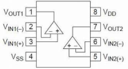
What a great topic! Thanks for all the information you shared. This allowed me to replace the CX-0461 with an OPA2134.
 

Attachments

  • 20251127_115341.jpg
    20251127_115341.jpg
    80.1 KB · Views: 34
  • 20251127_120226.jpg
    20251127_120226.jpg
    86.7 KB · Views: 32
  • 20251127_125558.jpg
    20251127_125558.jpg
    84.6 KB · Views: 30
  • OPA2134 Dual opamp pinout.png
    OPA2134 Dual opamp pinout.png
    37.5 KB · Views: 37
Last edited:
What a great topic! Thanks for all the information you shared. This allowed me to replace the CX-0461 with an OPA2134.
I should probably replace the OPA2134 with the OPA2604. Pin 4 (V-) and pin 8 (V+) measure 40V. I think that's too high for the OPA2134.... I just read the specifications and they mention max. 36V.
 
Last edited:
Back
Top Bottom