This is interesting. I also think that there was something important if Sony has done things like that, so maybe there is some reason. But why not put there that heatshrink tube and new grease with those 1N4148 diodes and bend it to contact the transistor just like the old ones was. I think theres nothing bad to do like this?


You are using an out of date browser. It may not display this or other websites correctly.
You should upgrade or use an alternative browser.
You should upgrade or use an alternative browser.
Sony TA-5650 v-fet matching and 1N4148 diodes
- Thread starter Jeff W.
- Start date
Hello again, now i have collected all the parts (allso ordered those united chemicon main capacitors from Texas) because i readed some bad things about those samwhas  So now it seems that my technician starts with my 5650 on next week. is there any precautions or something else i could give him because i want to be sure that everything goes well? I mean something like testing the amp without those vfets after recapping and if it seems to be ok, after that install those vfets? Or something else like this? Did you Jeff W changed any potentiometers to your amp?
So now it seems that my technician starts with my 5650 on next week. is there any precautions or something else i could give him because i want to be sure that everything goes well? I mean something like testing the amp without those vfets after recapping and if it seems to be ok, after that install those vfets? Or something else like this? Did you Jeff W changed any potentiometers to your amp?
Yes, checking voltages before installing the V-fets has been recommended by Echowars and is a good safety precaution. Clean the old grease from the V-fets when removed, then use new mica insulators and fresh grease when installing. Remember: never use a Variac to bring the power up on this amp. It did install new Bourns multi-turn, sealed pots on my driver board.
Ok. There is veeery long story but it ends like this that i did this recap by myself , anywhy after recapping i started to do adjustments, everything else checked ok but when i measured dc bias on left channel my emitter shows 19.0 vdc?? Right channel shows 60mv.
When i try to rotate this pot RV301 (service manual says RT301) nothing changes, is there possible faulty trim pot?
When i try to rotate this pot RV301 (service manual says RT301) nothing changes, is there possible faulty trim pot?

ilimzn
Well-Known Member
Alekk, something is very wrong, probably a dead source resistor (0.xx ohms, don't remember off hand).
Jeff, the dual diode is close to a transistor (about 0.2 inches or so) and normally it is just bent toward the transistor and covered in silicone grease. The easiest way to do the thermal contact (and I do recommend it because the bias will not be stable) is making the leads just a bit longer so that the two series diodes can be bent toward the transostor case and make mechanical contact with it. Apply some thermal grease between the diodes and the case, and then put a small ring of heat shrink tubing around the lot (diodes and transistor) and heat shrink it so that they remain in mechanical contact. That's all that's needed.
Before installing VFETs definitely test the bias voltages!!! This can be done with the amp powered up without the VFETs and without any load.
Regarding your earlier question regarding VFET rank - all VFET amps except the TA-N7 that have multiple VFET pairs, use them connected dead parallel without any way to enforce current sharing except using the same rank.
So, in all of these, all the K60 should be the same rank, all the J18 should be the same rank. However, a 1 rank of difference can be tolerated between the K60 and J18, although this is a suboptimal solution, however, given that VFETs are ever more difficult to get... First generation VFET amps also perform somewjat better the higher the VFET rank. In particular the TA-4650 can benefit given that it only has one pair per channel. The rest have the less benefit the more VFETs in parallel.
The TA-N7 and TA-F7 are more tolerant to rank differences for reasons I won't go into here. They can tolerate 1 rank difference even amongst the K60s or J18 BUT if at all possible there should be no more than 1 rank difference between the lot (so, things like K60 rank 3 and 4, and J18 rank 4 and 5 shluld be avoided in the same channel).
Jeff, the dual diode is close to a transistor (about 0.2 inches or so) and normally it is just bent toward the transistor and covered in silicone grease. The easiest way to do the thermal contact (and I do recommend it because the bias will not be stable) is making the leads just a bit longer so that the two series diodes can be bent toward the transostor case and make mechanical contact with it. Apply some thermal grease between the diodes and the case, and then put a small ring of heat shrink tubing around the lot (diodes and transistor) and heat shrink it so that they remain in mechanical contact. That's all that's needed.
Before installing VFETs definitely test the bias voltages!!! This can be done with the amp powered up without the VFETs and without any load.
Regarding your earlier question regarding VFET rank - all VFET amps except the TA-N7 that have multiple VFET pairs, use them connected dead parallel without any way to enforce current sharing except using the same rank.
So, in all of these, all the K60 should be the same rank, all the J18 should be the same rank. However, a 1 rank of difference can be tolerated between the K60 and J18, although this is a suboptimal solution, however, given that VFETs are ever more difficult to get... First generation VFET amps also perform somewjat better the higher the VFET rank. In particular the TA-4650 can benefit given that it only has one pair per channel. The rest have the less benefit the more VFETs in parallel.
The TA-N7 and TA-F7 are more tolerant to rank differences for reasons I won't go into here. They can tolerate 1 rank difference even amongst the K60s or J18 BUT if at all possible there should be no more than 1 rank difference between the lot (so, things like K60 rank 3 and 4, and J18 rank 4 and 5 shluld be avoided in the same channel).
Ok, so where do i start or should i just get it to somebody who knows better these things. All that i can tell is amp was working before i started then i changed all electrolytic caps and those doublediodes and change better binding posts, nowhere else is touched. v-fets is not installed to the amp yet.
is it posiible that those diodes are installed wrong?
i did install those diodes like you describe.
can you tell ilimzn which board i shoul start looking?
is it posiible that those diodes are installed wrong?
i did install those diodes like you describe.
can you tell ilimzn which board i shoul start looking?
Last edited:
 I checked those bias one more time and now i got 10mv on right channel and 17.5V on left channel.
Well, I would not argue with ilimzn, but the transistors that the diodes come in contact with (Q310 and Q360) are the pre-drivers, and even when running the amp hard, I don't measure but a few degrees temp rise over ambient. But I have always left the leads long enough that the diodes will heat up simply from the heat rising through the chimney from the main heatsink on the output devices.
But if we are going to discuss 'best practices', then heatsink compound and heatshrink is a good idea. I have not always religiously followed this method, since IMO the heat through the chimney allows for a Vf drop on the diodes about as much as any heating from the pre-driver.
Alekk, the stock bias trimpots may be an issue. That, and you MUST double-check all the capacitors that were changed. And if you haven't already, you need to separate the preamp from the power amp by removing the pre/main jumpers on the back panel (and ideally inserting shorting plugs into the power amp input RCA jacks).
What caps were used to replace the originals? I thought I read something about Samwah caps. Bad choice.
Also, read these (the PDF simply lists changes made to later production models to improve reliability of the amp):
But if we are going to discuss 'best practices', then heatsink compound and heatshrink is a good idea. I have not always religiously followed this method, since IMO the heat through the chimney allows for a Vf drop on the diodes about as much as any heating from the pre-driver.
Alekk, the stock bias trimpots may be an issue. That, and you MUST double-check all the capacitors that were changed. And if you haven't already, you need to separate the preamp from the power amp by removing the pre/main jumpers on the back panel (and ideally inserting shorting plugs into the power amp input RCA jacks).
What caps were used to replace the originals? I thought I read something about Samwah caps. Bad choice.
Also, read these (the PDF simply lists changes made to later production models to improve reliability of the amp):
Attachments
Hello Echowars, im glad you joined to conversation.
Most caps are Panasonic FR´s then few FC´s ,few rubycon´s and one sunoco or something. Main caps are same as you have earlier recommend, nippon chemicons.( I thinked two times with those samwhas and ordered new ones )
)
I have measured all vfets although they were removed from the amp when it still was fully working and didnt put them back eversince. (still im not sure why my 2sk60 do not show nothing on the measure D--to--G)
Hmmm, dont know how to measure capasitors with emitter? And didnt find any info yet. Is it even possible with emitter without capasitance measurement.?
Founded info from internet
No i havent separate those preamp and poweramps, i will do it.
(and ideally inserting shorting plugs into the power amp input RCA jacks). what you mean with this, didnt understand and not did google translator neither
Most caps are Panasonic FR´s then few FC´s ,few rubycon´s and one sunoco or something. Main caps are same as you have earlier recommend, nippon chemicons.( I thinked two times with those samwhas and ordered new ones
)I have measured all vfets although they were removed from the amp when it still was fully working and didnt put them back eversince. (still im not sure why my 2sk60 do not show nothing on the measure D--to--G)
Hmmm, dont know how to measure capasitors with emitter? And didnt find any info yet. Is it even possible with emitter without capasitance measurement.?
Founded info from internet
No i havent separate those preamp and poweramps, i will do it.
(and ideally inserting shorting plugs into the power amp input RCA jacks). what you mean with this, didnt understand and not did google translator neither
ilimzn
Well-Known Member
Alekk, you cannot measure any bias without the VFETs installed! Are you sure you know what you are measuring?
BIAS measurement in the 4650/5650 is done by measuring the voltage drop across one of the current detect resistors (0.47 ohms in the 4650, 0.33 ohms in the 5650). One side of the resistor is connected to the output, the other to a test point in each of the top corners of the driver board. On the 5650 the resistors are R395 and R345 (as far as I can read on the rather bad scan of the service manual I have here). Because of this, the manual states to measure between the speaker output (+) and the test point. BUT! this assumes that the speaker protection relay, the speaker select switch and the speaker connectors all work properly, and of course that the appropriate speaker output is switched on. Note - on the 4650 the speaker switch has to be set to 'A' and the measurement must be performed with one side of the meter plugged into the appropriate speaker output.
Bias current through these resistors is only developed by the VFETs - no VFETs installed, no bias current.
OFFSET measurement is done by measuring the voltage across the speaker terminals (with no speaker installed!), and all the notes regarding speaker switch and relay apply. Offset cannot be adjusted in these amps, but must be verified, if something is not right there, you cannot proceed to VFET installation and bias adjustment.
HOWEVER - there is an alternate way to measure the output offset and bias. When the bias is set to minimum, the drain of each VFET is connected to the output of the amplifier circuit, before the output relay and speaker switch, wiring, etc. When the 'chimney' in front of the component side of the driver board is removed, the contacts of the VFET sockets are exposed, and in particular the drain (housing) ones are fairly easy to get to. You can check the offset by measuring between the drain contact (where the screw that holds the VFET goes in) and a good ground, eg. the (-) speaker terminals for speaker pair A (this also applies to the 4650).
Once this is verified, the ability of the driver to generate proper bias should be checked. For this the buas setting pot must be at it's LOWERY resistance (which must be the default before installing VFETs anyway).
Only once the above is verified can you proceed with VFET installation.
NOW the easiest way to check bias is between th screw contact of the K60 (any one within the channel you are measuring) and J18 (also any one within the channel you are measuring) - but the readouut MUST be double what the manual says. This is because you are now measuring the total voltage drop over two emitter resistors, not just one.
BIAS measurement in the 4650/5650 is done by measuring the voltage drop across one of the current detect resistors (0.47 ohms in the 4650, 0.33 ohms in the 5650). One side of the resistor is connected to the output, the other to a test point in each of the top corners of the driver board. On the 5650 the resistors are R395 and R345 (as far as I can read on the rather bad scan of the service manual I have here). Because of this, the manual states to measure between the speaker output (+) and the test point. BUT! this assumes that the speaker protection relay, the speaker select switch and the speaker connectors all work properly, and of course that the appropriate speaker output is switched on. Note - on the 4650 the speaker switch has to be set to 'A' and the measurement must be performed with one side of the meter plugged into the appropriate speaker output.
Bias current through these resistors is only developed by the VFETs - no VFETs installed, no bias current.
OFFSET measurement is done by measuring the voltage across the speaker terminals (with no speaker installed!), and all the notes regarding speaker switch and relay apply. Offset cannot be adjusted in these amps, but must be verified, if something is not right there, you cannot proceed to VFET installation and bias adjustment.
HOWEVER - there is an alternate way to measure the output offset and bias. When the bias is set to minimum, the drain of each VFET is connected to the output of the amplifier circuit, before the output relay and speaker switch, wiring, etc. When the 'chimney' in front of the component side of the driver board is removed, the contacts of the VFET sockets are exposed, and in particular the drain (housing) ones are fairly easy to get to. You can check the offset by measuring between the drain contact (where the screw that holds the VFET goes in) and a good ground, eg. the (-) speaker terminals for speaker pair A (this also applies to the 4650).
Once this is verified, the ability of the driver to generate proper bias should be checked. For this the buas setting pot must be at it's LOWERY resistance (which must be the default before installing VFETs anyway).
Only once the above is verified can you proceed with VFET installation.
NOW the easiest way to check bias is between th screw contact of the K60 (any one within the channel you are measuring) and J18 (also any one within the channel you are measuring) - but the readouut MUST be double what the manual says. This is because you are now measuring the total voltage drop over two emitter resistors, not just one.
HOWEVER - there is an alternate way to measure the output offset and bias. When the bias is set to minimum, the drain of each VFET is connected to the output of the amplifier circuit, before the output relay and speaker switch, wiring, etc. When the 'chimney' in front of the component side of the driver board is removed, the contacts of the VFET sockets are exposed, and in particular the drain (housing) ones are fairly easy to get to. You can check the offset by measuring between the drain contact (where the screw that holds the VFET goes in) and a good ground, eg. the (-) speaker terminals for speaker pair A (this also applies to the 4650).
Ilimzn i got same results in this measurement than that what i did before(service manual 2-4 DC BIAS ADJUSTMENT), right channel 10mv and left 17.5VDC
Echowars
I allso double checked all electrolytics and there was nothing special everything seems to be ok. Checked those later model production mods and all was there, only resistor R371 was 4,6 Kohm (manual asks 4,3Kohm)
Allso pre and main amps was separated when doing this measurement.
Here in Finland we have this saying, don`t start fixing anything if it works,and again this proved right.

Still I'm glad that i get help from you guys

Ok so tell me what i need to measure before i can put the v-fet to their places.? I have gone trough all the adjusts what SM says .Only last section dc-bias adjustment give me something what i have worried. But if this last measurement can't be done without v-fets should i just put them on the amp?
ilimzn
Well-Known Member
Well, I would not argue with ilimzn, but the transistors that the diodes come in contact with (Q310 and Q360) are the pre-drivers, and even when running the amp hard, I don't measure but a few degrees temp rise over ambient. But I have always left the leads long enough that the diodes will heat up simply from the heat rising through the chimney from the main heatsink on the output devices.
But if we are going to discuss 'best practices', then heatsink compound and heatshrink is a good idea. I have not always religiously followed this method, since IMO the heat through the chimney allows for a Vf drop on the diodes about as much as any heating from the pre-driver.
Glenn, the diodes do not compensate for the changes in temperature of the output stage. VFETs have practically zero temperature coefficient, but the predrivers do not. This is not an issue of thermal runaway like on regular amps, just bias stability.
The predriver/driver setup is such that every mV difference across the predriver bases multiplies by about 33, so the difference in the bias this produces at first glance is not problematic given that the tempco of the semiconductors is ~2mV/degC. However the arrangement of the circuit penalizes lower VFET ranks - the lower the VFET rank, the lower the bias voltage is required for the same bias current. In this sort of driver setup, this also means that more bias voltage is required across the predriver bases, increasing the temperature dependency of the system (because the same drop across 3 diodes is just divided down by the bias pot, so is the temperature dependent part).
On the 5650 the issue is smaller because of the chimneys - airflow is well controlled so the internal temperature of the amp is less influenced by the heatsink and rises or falls slower, alowing the system to stabilize well. On the 4650 less so, no chimneys - hot air goes everywhere. Depending on how hard the amp is driven, the bias can go quite a bit higher once the lid is on, unlike the lid off condition when it is adjusted. Also, winter/summer temperatures may affect it. Taking into account all extremes, you can a nearly 4V change in bias voltage from extreme to extreme, which for rank 4 VFETs will almost double the bias current. Fortunately, since the predrivers and the diode are close and we are talking ambient temp, such a situation is virtually impossible (unless some idiot 'tech' uses something like cold spray on the predriver while the amp is working!!!) - BUT I have seen 100mA set up open become 125mA closed, with a temporary rise to about 135 since the predrivers also generate their own heat - until everything stabilizes. Depending on actual conditions, the 'hump' before stabilisation may be larger on low rank VFETs, and sadly, with less and less being available to fix the amps, one may be faced with an option to use rank 3, 2, 1... (yes they can be used but provisions such as this have to be made, rank 2 and 1 must be checked on a tracer and selected, especially for the 4650). Now, it's not that VFETs are extremely sensitive to the bias current tolerance, but it can be a nuisance, and a bit of thermal goop and heat shrink solve that.
ilimzn
Well-Known Member
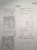
Here 2-4 DC BIAS ADJUSTMENT
This is where i get those results without v-fets installed
And did the manual say that the VFETs should not be installed for this measurement???

What do you get in step 2.3?
Please try measuring the following - still all with VFETs not installed:
Put (-) probe of your voltmeter to ground (any (-) terminal for speakers)
With (+) probe measure every pin on each VFET socket. So a total of 24 measurements.
BE VERY CAREFUL not to accidentally make a contact between pins!!!
No it doesent but i want to be extra careful because i love this amp 
Step 2.3 was meter in millivolt position 00.3 in both channels
Those vfet sockets shows so many different volts that maybe its better to know what im searching for? Allso should i measure from vfet drain too (screw holes) or just pins?
Step 2.3 was meter in millivolt position 00.3 in both channels
Those vfet sockets shows so many different volts that maybe its better to know what im searching for? Allso should i measure from vfet drain too (screw holes) or just pins?
ilimzn
Well-Known Member
All pins, so G, S, D on all of them
They go J18-J18-K60-K60 and K60-K60-J18-J18. As you can see they are in pairs pairs should show same voltages on S, D, and G. If not, this means a problem. I am trying to save you from many more measurements as doing all of them will show immediately if something is wrong on each channel, and then we can go on from that.
Very important, the 4-pin connector on the top of the driver board must be plugged in!
Correct voltages would be something like this:
J18 (S) 45 or so (main power supply)
J18 (D) 0
J18 (G) 55 or more
J18 (S) 45 or so (main power supply)
J18 (D) 0
J18 (G) 55 or more
K60 (S) -45 or so (main power supply)
K60 (D) 0
K60 (G) -55 or more
K60 (S) -45 or so (main power supply)
K60 (D) 0
K60 (G) -55 or more
The rest the same just reversed, K60 first, J18 last
The pins on the sockets go in this order if you start from the side of the board with ony one 5-pin wire wrap connector (it is the left side in the service manual but I don't know how it is easier for you to maasure)
Oh yes - one more question - does the output relay click?
They go J18-J18-K60-K60 and K60-K60-J18-J18. As you can see they are in pairs pairs should show same voltages on S, D, and G. If not, this means a problem. I am trying to save you from many more measurements as doing all of them will show immediately if something is wrong on each channel, and then we can go on from that.
Very important, the 4-pin connector on the top of the driver board must be plugged in!
Correct voltages would be something like this:
J18 (S) 45 or so (main power supply)
J18 (D) 0
J18 (G) 55 or more
J18 (S) 45 or so (main power supply)
J18 (D) 0
J18 (G) 55 or more
K60 (S) -45 or so (main power supply)
K60 (D) 0
K60 (G) -55 or more
K60 (S) -45 or so (main power supply)
K60 (D) 0
K60 (G) -55 or more
The rest the same just reversed, K60 first, J18 last
The pins on the sockets go in this order if you start from the side of the board with ony one 5-pin wire wrap connector (it is the left side in the service manual but I don't know how it is easier for you to maasure)
Oh yes - one more question - does the output relay click?
Last edited:
ilimzn
Well-Known Member
There are multiple problems here. There is a ground missing or an incorrectly installed capacitor somewhere in the power supply or a short on the negative bias voltage supply. Also, the re is a missing positive main supply on the sources of the left side on the board, the right side is ok.
When measuring please DO write the minus sign (-) in front of the measurement, it is important that I know the voltage is negative, not just the number.
Next step:
measure the voltages on the pins of the 5-pin connectors on the left and right side of the board. Still the same system, the - probe remains connected to gnd, and you measure with the + probe.
From what I can tell, some of the wires have lost connection, have broken off or there is a bad solder joint. The relay should not click under these conditions (+17V on the output of the first channel!)
When measuring please DO write the minus sign (-) in front of the measurement, it is important that I know the voltage is negative, not just the number.
Next step:
measure the voltages on the pins of the 5-pin connectors on the left and right side of the board. Still the same system, the - probe remains connected to gnd, and you measure with the + probe.
From what I can tell, some of the wires have lost connection, have broken off or there is a bad solder joint. The relay should not click under these conditions (+17V on the output of the first channel!)