• The move to the new server is done. There are some software and database maintenance updates in process. This has us passing the hat around to help out. We appreciate any donations. Seriously, even a dollar helps. The payment page may be found here - https://www.audiokarma.org/support.html

Sony TC-580 help

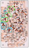
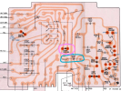
Here is the component side of the ESP board.
I have circled three transistors to measure. Be careful so you don't short out pins when you move the DMM probe.
Connect the black lead of your DMM to chassis ground.
Set your DMM to measure DCV.
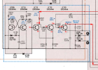
With the red lead, please measure the E (emitter), C (collector), and B (base) DCV for each of the transistors below:
  • Q711 (ECB)
  • Q712 (ECB)
  • Q713 (ECB)
Screenshot 2025-08-13 125424.png
 
sorry. I listed them in emitter, base, collector order. I got 25vdc on the power in red wire.
all measurements were with R2R in reverse mode which it always switches to.
James
 
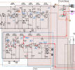
Thanks. Yes the voltages of Q713 show that it is in reverse mode. Shown in ( ) in the schematic.
Let's see what is causing it to be in reverse by tracing the voltages back to see if a transistor is bad.

Screenshot 2025-08-13 164736.png
Can you measure a few more voltages (circled in blue on the diagram).
Q709 EBC​
Q710 EBC​
R735 (both ends if you can get to them)​
R737 (both ends)​
R739 (both ends)​
Screenshot 2025-08-13 164524.png
 
EDIT:
You know looking at the schematic again, the voltages of Q713 and Q712 indicate that they are in reverse mode.
But, the voltages on Q711 show that it is in forward mode.
Maybe Q712 is bad? Do you have a transistor tester?
If bad, you can try to replace it with an KSC1845FTA. (Mouser)
----------------------------------------------------------------------------------
Thanks. I followed the signals and voltages that you measured.
You had the switch in "Non Reverse Mode" when you took the voltage measurements... Yes?
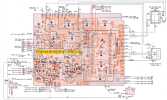
Here are your updated voltages on the PCB.
Screenshot 2025-08-14 074628.png

I followed the signal path to the long FWD/REV switch (S101) on the Bias OSC Circuit Board (highlighted in yellow).
  • If it looks like a long bar with some mechanical linkage to move it... that's the one. It also looks like there are two others on the same board.
  • If you can't find it, take a picture of the component side of the board and post it.
  • These long slide switches are typically know for getting oxidized contacts that need to be cleaned.
  • Do you have some Deoxit D5 spray?
  • If you can see any openings in the metal part of the switch or see the contacts, spray a bit into it and work the switch back and forth about 30-50 times to work it in.
  • Let it dry overnight, the see if it improves. Otherwise, we need to measure some more voltages.
Screenshot 2025-08-14 073629.png
 
Last edited:
I do have the switch set to non-reverse. I will spray that switch with deoxit and let know if that helps.
Thank you,
James
 
I will have to see if I have that transistor. I dont have many transistors.
That long switch appears to be one that have deoxited many times. Is it this one in my photo? I'm confused, does the solenoid control the switch or vise versa?
Thanks
James
 

Attachments

  • 17551869428842122740219213596222.jpg
    17551869428842122740219213596222.jpg
    107.6 KB · Views: 5
We probably should remeasure all of these voltages to get another baseline to troubleshoot from.
Here is what I have from the last time. According to the schematic, the voltages in ( ) are for reverse, otherwise forward.
If you look at your previously measured voltages, you will notice that voltages for Q713 are for reverse while Q709, Q710 and maybe Q711 are for forward.
We need to find out why they don't match.

Screenshot 2025-08-15 085945.png
 
While you are in there measuring, can you measure the voltages on both sides of R741 (circled in pink) with black lead on ground?

Screenshot 2025-08-15 094121.png
 
dankik,
I measured in emitter, collector, base order this time.
q713. 0,0,.75v
q712. 0,20v, 0
q711. 0,0,0
q709. 0,0,0
q710. 0,0,0
r735. 0,0
r737. 0,0
r739. 0,0

I believe the first time I measured r739 I got the wrong connection. some of the zero readings were actually a few mv.

thanks
james
 
OK, can you get to the power supply board? It looks like this (back side):
Can you please measure R610, both sides. They should be 24VDC at least on one side.
This is the voltage that goes to relay RY601 for reversing.

Screenshot 2025-08-15 110703.png
 
Let's move up to the relay coil voltage. Please measure the voltage on each side of D603, circled in pink (with black lead on ground).
Screenshot 2025-08-15 110703.png
 
Back
Top Bottom