

You are using an out of date browser. It may not display this or other websites correctly.
You should upgrade or use an alternative browser.
You should upgrade or use an alternative browser.
Sony TC-580 help
- Thread starter dadjmon
- Start date


??? 109mV on the right side.109 mg on the right side
Tennangler
Well-Known Member
yes
OK. Let's see if the relay is working.

- With power OFF.
- Set DMM to measure Ohms between relay contacts shown on the board diagram below.
- Measure Ohms between red circle and green circle
- Measure Ohms between red circle and blue circle
- This will tell us the relay contact position when there is no voltage on the relay coil.
Tennangler
Well-Known Member
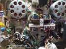
Tennangler
Well-Known Member
relay ry602 on the relay circuit board is the one not moving. I'm not sure what it controls.
Tennangler
Well-Known Member
As soon as I turn the power on the R2R will reverse and RY601 will move. It will not go into forward when I push the forward button. So, I made all measurements in the reverse mode.
James
James
Let's try this... maybe the Rev Play Switch is mis-adjusted so that it is always pressed (i.e. closed) causing the recorder to always go into Rev Play as soon as power is applied."As soon as I turn the power on the R2R will reverse and RY601 will move. It will not go into forward when I push the forward button. So, I made all measurements in the reverse mode."
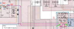
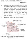
Can you check the adjustment of the Fwd Play (S615) and Rev (S616) Play Switches.
If you can get to the switch wires, WITH POWER OFF you might be able to check to see if the Rev switch has continuity between the two wires. There should only be two wires going to each switch and if I read understand the operation, use your DMM set to Ohms and measure across the terminals where the two wires are soldered. They should read OL when measured across the two wires (open) and 0 Ohms (short) when the Fwd or Rev button is pressed. Check both switches.
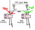
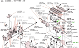
If not, here are the instruction and switch locations from the SM.
Last edited:
Tennangler
Well-Known Member
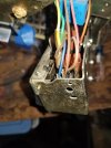
I have not been able to find those switches. they may be under the stopper release plate. I'm concerned the springs will come off and cant get it back together. Do you think this is where they are?
I will be gone all day and will check back this evening.
Thank you for all your help.
James
I will be gone all day and will check back this evening.
Thank you for all your help.
James
Attachments
Tennangler
Well-Known Member
I am trying to send a video of what happens when I turn it on but AUdiokarma dont like the format my android videos are in. Any suggestions?
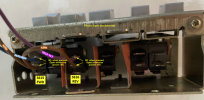
Here is what I think your picture shows in relation to the switch diagram. I can't see where the VLT wire goes???
If you look at the underside of that switch assembly, I think you should be able to see the bare switch contact leaf and contacts.
If you can get a better picture of that 2nd switch and wires I could confirm it is correct. Also, a picture of what it looks like on the underside.
With power OFF, you should be able to connect your DMM set to measure Ohms to the blue wire and brown wire.
When you press the FWD Play button you should read 0 Ohms. When you release it, it should read some other resistance.
The next switch is the REV Play button. It should work the same way. If it remains at 0 Ohms, then the switch is bad. Let me know.
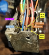
It looks like a different type of switch is used vs what is shown in the SM.
I found a better photo showing wiring here:
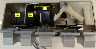
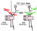
Here is where the BLU and VLT wires go to on the ESP circuit board.
One way to test the Rev Play switch to see if it is always closed is to use your DMM set to measure volts and measure the voltage on the VLT wire on the ESP board at point 27 when you turn power on. It should be 0v, but if you measure 24v then it is stuck ON.

If you look at the underside of that switch assembly, I think you should be able to see the bare switch contact leaf and contacts.
If you can get a better picture of that 2nd switch and wires I could confirm it is correct. Also, a picture of what it looks like on the underside.
With power OFF, you should be able to connect your DMM set to measure Ohms to the blue wire and brown wire.
When you press the FWD Play button you should read 0 Ohms. When you release it, it should read some other resistance.
The next switch is the REV Play button. It should work the same way. If it remains at 0 Ohms, then the switch is bad. Let me know.
It looks like a different type of switch is used vs what is shown in the SM.
I found a better photo showing wiring here:
Here is where the BLU and VLT wires go to on the ESP circuit board.
One way to test the Rev Play switch to see if it is always closed is to use your DMM set to measure volts and measure the voltage on the VLT wire on the ESP board at point 27 when you turn power on. It should be 0v, but if you measure 24v then it is stuck ON.
Last edited:
Tennangler
Well-Known Member
I was able to easily access those switches from the top.
blue to brown read "ol". when the forward switch was pushed it read "1 ohm".
violet to brown read "ol". when the reverse switch was pushed it read "1ohm".
It appears the switches are working as they should.
James
blue to brown read "ol". when the forward switch was pushed it read "1 ohm".
violet to brown read "ol". when the reverse switch was pushed it read "1ohm".
It appears the switches are working as they should.
James
Tennangler
Well-Known Member
I also measured the voltage from violet to brown on the ESP Board. got "0" with reverse switch off, 24vdc with it on.
I also measured the forward voltage from blue to brown. I taped the forward switch down, got 0 vdc. even with the forward switch taped down it was still turning in the reverse direction.
James
I also measured the forward voltage from blue to brown. I taped the forward switch down, got 0 vdc. even with the forward switch taped down it was still turning in the reverse direction.
James
When you measured these voltages, where exactly on the ESP board did you put the DMM leads? Can you show me on the drawing above (or board below)?I also measured the voltage from violet to brown on the ESP Board. got "0" with reverse switch off, 24vdc with it on.
I also measured the forward voltage from blue to brown. I taped the forward switch down, got 0 vdc. even with the forward switch taped down it was still turning in the reverse direction.
I'm not sure all brn wires carry the same voltage. Can you measure voltage with black lead connected to chassis ground?
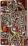
Last edited:
Tennangler
Well-Known Member
I measured between brown and violet in the bottom right of the photo for reverse mode. Between the same brown and the blue on the left side off the board for forward mode.
When measuring with the black probe on chassis ground I got zeros for reverse when on and off. In forward mode I got 22vdc with the button held down with tape, zero with button released. As I explained before, the reels still turn in reverse even with forward button pushed.
James
sorry, I dont know how to copy a photo and draw on it.
When measuring with the black probe on chassis ground I got zeros for reverse when on and off. In forward mode I got 22vdc with the button held down with tape, zero with button released. As I explained before, the reels still turn in reverse even with forward button pushed.
James
sorry, I dont know how to copy a photo and draw on it.
Hi, thanks. That brown wire that you measured is a different brown wire than the one that goes to the switches.I measured between brown and violet in the bottom right of the photo for reverse mode. Between the same brown and the blue on the left side off the board for forward mode.
Let's try this:
- DMM black on chassis ground. (I traced the ground and it looks like the WHT/RED wire on the bottom left of the ESP Board is tied to ground so you can also use that for your black DMM lead if it is easier).
- DMM red lead on violet wire on the ESP board.
- What voltage do you read (assuming it is in reverse play)?
- Press Fwd Play while still measuring the voltage on the violet wire. What do you get if you hold the button down?
- What do you get after you release the button?
- Now, DMM red lead on the blue wire (black lead still on chassis ground)
- While it is still playing in reverse, what voltage do you read on the blue wire?
- Now, press the fwd play button and hold it down. Now what voltage do you read on the blue wire?
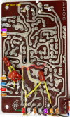
I hope that's a little clearer.
Last edited:
Tennangler
Well-Known Member
black probe on chassis ground.
violet wire in reverse, a few mv, basically 0
press forward play. violet wire is no change. the R2R does not come out of reverse play.
blue wire in reverse. 0vdc
blue wire holding forward play down 22vdc
James
violet wire in reverse, a few mv, basically 0
press forward play. violet wire is no change. the R2R does not come out of reverse play.
blue wire in reverse. 0vdc
blue wire holding forward play down 22vdc
James
Something doesn't make sense??? You are getting 0v on the violet lead whether pressed or not. Either the 24v is not getting through the switch or one side of the switch is tied to ground somewhere?


- With the DMM black lead on chassis ground
- Measure the DC volts on the brown lead of S616 (Rev Play) with the switch not pressed (red arrow)
- Next, press and hold the S616 switch and measure the brown lead again
- Measure the DC volts on the violet lead of S616 (rev Play) with the switch not pressed (red arrow)
- Next, press and hold the S616 switch and measure the violet lead again
Last edited:
Tennangler
Well-Known Member
I'm getting 22vdc on the brown wire when pressed or not.
I'm getting 0vdc on the violet wire when pressed or not.
James
I'm getting 0vdc on the violet wire when pressed or not.
James