• The move to the new server is done. There are some software and database maintenance updates in process. This has us passing the hat around to help out. We appreciate any donations. Seriously, even a dollar helps. The payment page may be found here - https://www.audiokarma.org/support.html

Sony TC-580 help

violet to brown read "ol". when the reverse switch was pushed it read "1ohm".
We know that that switch works because of the test in post #53. Or maybe it is intermittent.
But, the 22v is not getting to the violet wire side of the switch... so my guess is that the violet wire is being forced to ground somewhere.
Just to confirm, your measurements above were made at the terminals on the play reverse switch S616... correct?

First, can you resolder the brown and violet wires on the switch.
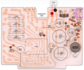
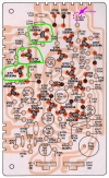
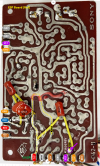
Next, with POWER OFF, measure the resistance (Ohms) between the violet wire on the switch terminal (S616) and R727 on the ESP Circuit Board (as shown with violet arrow).
Screenshot 2025-08-17 172343.png
 
I havnt resoldered the wires yet but I do have continuity on the violet wire from the switch to the ESP board.
I will resolder tomorrow.
thanks
james
 
OK. Also check to make sure that you do not have a solder whisker between the violet pad and gray pad next to it.
 
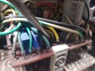
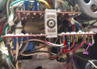
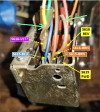
Can you tell me if there is a 2nd half of the Fwd Play switch. I can't tell from your photo, but it looks like there are a 2nd set of wires (green arrows) YEL, GRN, and RED. Where do they connect to the switch and where do they go? Is there a bar that presses on both the Fwd Play and this 2nd switch at the same time (2nd photo)?
A better photo of this would be good. I don't seem to see it in the schematic.

Screenshot 2025-08-18 083604.png Screenshot 2025-08-18 084450.png
 
Last edited:
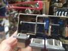
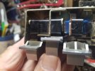
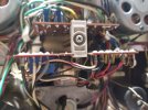
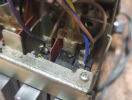
There is a switch between the forward and reverse switches. pushing forward button also pushes that center switch (1st photo). Pushing the reverse switch also pushes the center switch (2nd photo).
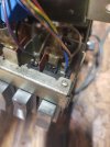
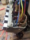
The third photo shows wires to that center switch. The green and yellow go to the front pin and the orange wire goes to the back pin.
20250818_110401.jpg20250818_110404.jpg20250818_110642.jpg
 
ok, I made continuity checks to confirm where the center wires went . The green wire goes to switch on the left in the first photo.
The orange one goes to the switch on the right.
the yellow goes to the relay board (2nd pic).20250818_113802.jpg20250818_113902.jpg
 
I don't think that the center push button switch is a problem, but for completeness here is the function of those two switches.
Screenshot 2025-08-18 102834.png
 
Last edited:
I checked the B+ voltage on the power supply board per the service manual. I got -21 vdc. Should be +24vdc. could not adjust R603 for correct voltage. I put it back to the original position after spraying with deoxit.
What could that be?
Thanks,
James
 
Sorry, I can't make out the circuit board from this photo.
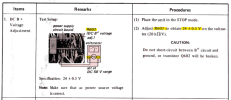
As near as I can tell from the SM, here is where to measure the +24v.
Screenshot 2025-08-18 143539.png
Screenshot 2025-08-18 143352.png
 
Last edited:
So, I think the black DMM lead would connect to the black wire,
The red DMM lead would connect to the white/red wire.
Adjust VR for a =+24V reading.
I got -21 vdc.
Maybe you had the DMM +/- leads reversed?

Screenshot 2025-08-18 144410.png
 
Last edited:
OK, I thought the SM was pointing to the black and blk/white wires on the left of the photo.
I measured the ones you showed me and was able to adjust to 24vdc.
any ideas what I try now?
Thank you
James
 
Can you please check this violet wire here. The bare wire is long and could be shorting to the metal (it's hard to tell from your photo).
Can you verify again that the voltage on the violet wire AND the brown wire, both with the switch open (not pressed) and closed (held pressed)?
Your previous measurements indicated that it was 0v in either position, but the brown wire was 22v?

Screenshot 2025-08-19 091453.png
 
That wire sticking out is just a spring that returns a switch button.
The violet wire reads 0 (250mv) whether open or closed. the brown wire is 22vdc in both position.
James20250819_123936.jpg
 
Thanks. Try this again. WITH POWER OFF, measure the resistance (Ohms) between the violet and brown wires (on the switch) when the switch is in the open and closed positions.
One more thing, again with power off, measure the resistance between the violet wire (on the switch) and chassis ground.
 
Last edited:
with switch open "OL"
with switch closed. 0 ohms
violet wire to ground "OL"

I measured the blue wire too. same readings as the violet wire.
 
Hmmm.... I would like to find out why it does not change from 0v.
  1. Please unsolder one end of resistor R727 (purple arrow on board)
  2. Now, with power on measure the voltage of the violet wire (at the switch) again with the switch pressed and open.
  3. It should be 0v when switch is open and 22v when switch is closed.
  4. Measure the voltage on both the lifted end of R727 and the other end of R727.
  5. Next, WITH POWER OFF, use your DMM to measure the resistance (Ohms) of R727. Probes across both resistor leads.
Screenshot 2025-08-19 114930.png
 
Back
Top Bottom