

You are using an out of date browser. It may not display this or other websites correctly.
You should upgrade or use an alternative browser.
You should upgrade or use an alternative browser.
Sony TC-580 help
- Thread starter dadjmon
- Start date

Tennangler
Well-Known Member
I can try measuring Q713 again while holding the forward play button down. The machine will still play in reverse while I'm holding it down.
Tennangler
Well-Known Member
I measured q713 again. got 0, 0,, .7v.
got the same measurments with forward play is held down or not.
Again. the unit is running in reverse while I'm making these measurments
James
got the same measurments with forward play is held down or not.
Again. the unit is running in reverse while I'm making these measurments
James

Your switches seem to be slightly different than the internet photo. Can you verify something for me?

Here are two photos that you posted. The one on the left is more recent, one on the right older.

- The microswitch in the center (S608, the one that gets pressed when either fwd play or rev play gets pressed)
- It looks like there are 3 terminals on it, the red wire goes to the terminal that is on the bottom of the switch
- The yel and grn wires go to the middle terminal
- With power OFF, measure the Ohms between the red wire and the yel-grn wire. What do you measure?
- Same thing, but press and hold the button. What do you measure?
- Now, do the same between the red wire and the terminal with no wire connected to it. What do you measure?
- Also, do all 3 switches (S615, S616, S608) have a third terminal that is on the bottom side of the switch like the middle one? I can't tell from you photos.
EDIT: Also, please check out your wiring to the middle switch (S608).The third photo shows wires to that center switch. The green and yellow go to the front pin and the orange wire goes to the back pin. ???
Here are two photos that you posted. The one on the left is more recent, one on the right older.
- Photo on L shows the GRN-YEL wires going to the 2nd terminal and RED wire going to the bottom terminal. Terminal closest to the buttons is open.
- But the photo on Post #50 shows the GRN-YEL wires going to the terminal closest to the buttons.
- What was the original wiring?
- If you tell me which pair of terminals are open when not pushed and closed when pushed we can figure it out.
- Looking at the other switches, I think that if the switch not pressed, you should have OC between the red wire and the terminal closest to the buttons.
- When that switch is pressed, you should read 0 Ohms for the same red to top terminal. What do you get.
Last edited:
Tennangler
Well-Known Member
measuring red to yel/grn I get open.
when I hold the button down I get 0 ohms.
the other 3 switches have a wire going to the bottom of each one.
when I hold the button down I get 0 ohms.
the other 3 switches have a wire going to the bottom of each one.
Tennangler
Well-Known Member
I see what you say about post #50. I may have put it on the wrong terminal after I unplugged it to remove the bracket mounting screw.
I believe it is on the correct tab now.
James
I believe it is on the correct tab now.
James
OK, now you've got me confused. Tell me if this diagram is correct.


(Backside of switches.)
- Do the terminals that I have labeled "No Connect?" have no wire connected to them? Yes/No?
- If you measure the resistance for each switch, do you read OC when not pressed and 0 Ohms when pressed? Connect the meter to the following:
- S615, blue wire to brown wire?
- S608, green wire to red wire?
- S616, violet wire to brown wire?
- S608, red wire to No Connect terminal?
- Do all three switches physically look the same? Can you see a name and part no on the switches?
- EDIT: What exactly do you mean by this statement "the other 3 switches have a wire going to the bottom of each one." Are you referring to the ones I marked No Connect? Take a look at the 2nd photo below for S615. You can see that there are no wires connected to the bottom terminal (green arrow). What do you mean?
- If so, what color are the wires and where do they go to?
(Backside of switches.)
Last edited:
Tennangler
Well-Known Member
All the terminals you labeled "no connect" do not have wires connected to them.
The fwd, play. and rev. switches all read no continuity when they are not pressed.
All show continuity when they are pressed.
All the switches appear to be the same except the play switch has a brown button and other two have red ones. I am not able to see a name on them.
What I was referring to by "the other 3 switches with a wire going to the bottom" were the stop, ff, and rewind switches.
The terminal with the green arrow is the bottom terminal on the forward switch s615 that you have labeled no connect. I may have referred to it as the play switch in earlier posts before I saw your diagrams.
James
Tennangler
Well-Known Member
I want to explain the issues again since they have gotten worse. My original symptoms were just as Dadmon explained when he started this thread. Sorry for high jacking it. I hope this has solved your issuses.
Here are current issues. See photos for reference. Sorry I cant send a video as that would explain things better.
When the power switch is turned on, the forward arrow light comes on for a second then the fwr/rev solenoid clicks and the rev arrow light comes on.
when I push the forward play button it immediately starts playing in reverse.
additionally, when I push the ff button it immediately starts rewinding in reverse.
I hope this clears up any confusion as to what the issues are if it wasn't already understood.
Thanks
James

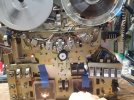
Here are current issues. See photos for reference. Sorry I cant send a video as that would explain things better.
When the power switch is turned on, the forward arrow light comes on for a second then the fwr/rev solenoid clicks and the rev arrow light comes on.
when I push the forward play button it immediately starts playing in reverse.
additionally, when I push the ff button it immediately starts rewinding in reverse.
I hope this clears up any confusion as to what the issues are if it wasn't already understood.
Thanks
James
Attachments

First of all, it looks like you don't have the tape threaded correctly. Compare the two photos below.

The Owner's Manual only says this... so I'm not sure.

Found another video on the internet and it seem to be threaded like you had it in your photo? It would make sense because with the head cover on, I don't think that you can get it around the tension arm in the other photo.

- Your tape path is in red, but as far as I can tell from your photo, you are on the wrong side of the tape tension arms (circled)
- Compare your photo to one that I found on the internet (I think this is correct).
- The tape goes around the tape guide and over the tension arm for both sides.
- The 2nd thing to notice is that your Reverse arrow light is on, but I think the pinch roller is in the forward play position.
- Compare yours to the one below it which is in Forward Play, the forward light is on and the pinch roller is in the correct position.
- Third thing, its hard to tell from your photo, but it looks like the Auto Rev switch is in the "REV" (middle) position, not the "NON REV" (down) position which should cause it to play in only one direction.
- Try to correct those errors and see what happens.
The Owner's Manual only says this... so I'm not sure.
Found another video on the internet and it seem to be threaded like you had it in your photo? It would make sense because with the head cover on, I don't think that you can get it around the tension arm in the other photo.
Last edited:
Tennangler
Well-Known Member
The tape is on the outside of the tension arms. I cant do that with the front plate on but didnt notice with it off.
The pinch roller will not move left or right when play is activated. I read that it is not necessary that it does. However, that may be a clue as to why the R2R wont play in the forward direction.
The reverse switch is in the non reverse position.
I threaded the tape correctly and moved the pinch roller to the right. I retested but none of that changed anything.
James
OK. I watched another video and what it looks like is that when you press STOP, the two tension arms retract into the silver housing that you see in the photo from the internet above. When you press FWD or REV Play, that little tension arm comes out of its little house and presses against the outside of the tape (as shown in the internet photo above). As soon as you press STOP again, that tension arm retracts into its house.The tape is on the outside of the tension arms. I cant do that with the front plate on but didnt notice with it off.
So with respect to your deck, maybe your tension arms are not moving in and out. In any event the photo from the internet is the tape path during Play (fwd or rev). With your covers off you should be able to see the tension arms move quite far out of the way of the tape path when in STOP and quickly move in next to the tape guide when in Play.
Also, regarding the position of the pinch roller (L or R of the capstan), for FWD Play the pinch roller should be on the right side of the capstan and for REV Play it should be on the left side otherwise the tape does not contact the Play head correctly causing poor muffled sound because it does not push the tape close enough to the tape head.
You can see this operation in the video.
I also started to look at the Service Supplement 2 which has a description of the tape transport direction changing operation. There is a section on the ESP circuit. In particular there is a section on when RY601 relay is energized and PM603 direction change solenoid is energized.
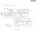

Last edited:
Tennangler
Well-Known Member
dankin,
The tension arms are working as they should.
The pinch roller is not moving when I change directions because the small roller behind the pinch roller is worn out and is not contacting the capstan. I can move it to either side manually.
I can see ry601 closing when I turn the power switch on. I measured Q604 and got nothing. If I push and release the forward play button I measure 22vdc on the collector but it still plays in reverse.
From what I'm reading it seems ry601 should not be closing. Does that make sense to you?
James
Where is Q604, I don't see it on the schematic or board layouts? Did you really mean Q704???I measured Q604 and got nothing.
RY601 closes when reverse play is selected, AFAIK. 24V is always there, but the other side of the relay coil is grounded by Q713 being turned on and one of the relay contacts holding it to ground, when I think it should be OFF unless you are in reverse play.
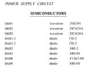
Last edited:
Tennangler
Well-Known Member
Sorry, typo, it is transistor q704 on the ESP circuit board.
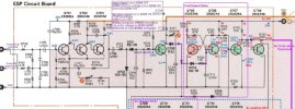
Tennangler
Well-Known Member
with music playing in reverse. ECB
0v, 22v, -5v
playing blank portion
0v, 22v, -6v
0v, 22v, -5v
playing blank portion
0v, 22v, -6v
That's curious... a -5v/-6v at the base of Q704??? There are no negative voltages around the circuit.
Now we need to trace the signal from the input to the ESP board to the base of Q704 and see where it is coming from.
Measure the ECB of Q701, Q702, Q703 under the same conditions (play music and play blank tape in rev).

Now we need to trace the signal from the input to the ESP board to the base of Q704 and see where it is coming from.
Measure the ECB of Q701, Q702, Q703 under the same conditions (play music and play blank tape in rev).
Tennangler
Well-Known Member
q701. with output. 0v,.5v,.6v
Q702. 0v, 300mv, .5v
q703 0v, 11v, 300mv
q701. blank tape 0v, .6v, 0v
q702. 0v, 300mv, 0v
Q703 0v, 11v, 5v
Q702. 0v, 300mv, .5v
q703 0v, 11v, 300mv
q701. blank tape 0v, .6v, 0v
q702. 0v, 300mv, 0v
Q703 0v, 11v, 5v