• The move to the new server is done. There are some software and database maintenance updates in process. This has us passing the hat around to help out. We appreciate any donations. Seriously, even a dollar helps. The payment page may be found here - https://www.audiokarma.org/support.html

Sony TC-580 help

that is r713.
The long leg of r745 is on the ground run so I had the r745 values backward.

I dont have a signal generator.
 
Do you have a 1kHz signal on a test tape? What about a PC or phone app signal generator?
For your PC, you might be able to use an app like this to generate a 1kHz tone.
Screenshot 2025-09-04 122206.jpg
 
Last edited:
First, let me say that I don't know if this is a problem or not. But, this is the point where you previously measured 22v (and it looks like it should be 10v).
Note the current position of R711 so you can return it there if it does not work out. Also, if you don't feel comfortable doing this... don't do it.

The instructions are a bit confusing, but the way that I read it is that you are injecting a 5.5mV sinusoidal signal into the LINE OUT (R) RCA jack.
I think the reason you inject the signal into the LINE OUT jack is because that is the signal that is used to trigger the auto reverse function (see schematic below).

Then you connect a voltmeter to the checking point (Q704 collector) and measuring the voltage.
It says place the unit in FWD mode, which I don't think you can do.
Then, adjust R711 until you get a 9.5v to 10.5v reading on the DMM.

Do this first then we can try the next steps.
Screenshot 2025-09-04 155802.jpg
Screenshot 2025-09-04 160541.jpg
 
I remeasured the collector of Q704 and got 22v again.
Since it wont play in forward I cant make the adjustment on R711 can I?
Can I adjust R711 randomly to see if it plays in forward mode?
 
I really don't know, but I am hoping that the 22v on Q704 collector is too high and causing it not to reverse.
  • The voltage at point "A" is basically the R-channel audio output so I don't think that it matters which direction the tape is moving and with the switch set to CONT REV with no audio it should continue to reverse back and forth after the delay.
  • First adjust your sinusoidal signal to 1kHz and the correct output level and connect it to the LINE OUT, R-channel RCA.
  • Mark the current position of R711 with a marker so you can put it back if this does not work.
  • Connect your DMM to Q704 collector or R716 where it connects to the collector. (where you measured the 22v)
  • Play a blank tape then see if when you adjust R711 one way the voltage at goes down from 22v down to 10v.
  • If the voltage starts to increase, then stop and turn it the other way.
  • If you can get the voltage down to 10v see if it makes any difference. If you can get it down, let me know what it does now that it is adjusted.
  • Check to see if the -8v on Q704 base changes.
Thanks.
 
How do you generate a 1kHz signal with an app on your phone?
You said "yes, I can record it to reel tape from my phone."​
I assume that you have a mini-stereo plug or USB-C plug to connect your phone to your RTR to record the signal as stated above.
Instead of plugging your phone into the Tape In jack of your RTR, plug it into the Tape Out jack (right channel).
If you can control the volume with your phone, then turn it down until you get the voltage output needed.
 
Last edited:
I understand plugging my phone into the R2R output. I dont know how to adjust to get the correct output level.
Also, could this damage my phone?
 
do I get the correct output level (5.5mv) by measuring the phones output with my DMM?
Yes. Measure with DMM on ACV.
I can't say whether it will damage your phone or not (use an old phone if you have one).
  • If you have an old PC with sound card output, you can use that with a software tone generator.
  • Since the output level is low as well as the 1kHz frequency and you really don't care about the purity of the signal (only the level), you could use an old cassette recorder or another RTR to record a1kHz tone, then play it back into the Sony while adjusting the output level control to get the desired output voltage level.
  • I don't even know if performing this adjustment will solve your reverse playback problem?
  • It just seems to me that since your measured voltage at the test point is 20v vs 10v (way off).
  • You might be able to just try adjusting the variable resistor a bit to see if that voltage changes. Maybe you can get it down and it will not start to play in reverse.
  • If it doesn't even change then there is likely another problem.
 
Last edited:
I adjusted R711 with my probe on the collector of Q704 and the voltage never budged from 22vdc. I adjusted all the way I could go in both directions.
 
I'm beginning to think that this problem is too difficult to troubleshoot over messages and your lack of test equipment. I would recommend that you take this to an experienced tech that knows about RTR tape recorders to troubleshoot. I would be glad to help or answer your questions, but it is difficult to follow signal paths to determine the problem without having the deck in front of me. Perhaps another AK member can chime in and help.
 
dankik,
I understand. You have spent a lot of time walking me through the troubleshooting process with diagrams and markups to explain things along the way. Most would not have spent that much time.
I hope there is someone who has had this issue that can shed some light on it. This appears to be a very common but difficult issue to resolve.
Thanks a lot for all your help.
James
 
Glad to help. I would hate to introduce additional problems in the course of troubleshooting this one. Did the TC580 ever work correctly, or did you get it with this problem?
 
It had the problem when I got it. Initially it played in forward for 3-4 seconds before reversing. Thought it would be an easy fix. Man was I wrong. It also use to ff. Now the ff goes into rewind as soon as I push the ff button. It will go in ff if I hold the ff button down (not release it)
As it is I can use it as a reverse machine only. I will try recording in reverse and see what happens.
Thanks again,
James
 
dankik,
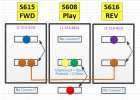
Do you have a diagram like in post #127 that shows which color wires connect to the rwd.,ff., and stop buttons?
Thanks
James
 
Here is the diagram that I have for the fwd and rev play. I did not trace the wires for stop, ff, rew.

Screenshot 2025-09-06 112855.jpg
 
Greetings from RojoLand!

Q704 collector remaining at 22 V means either it's turned off (which would certainly be true with a negative B-E voltage), OR Q704 could be open-circuit at the collector. Might be worth pulling and testing Q704 (2SC634A).

It looks to me like a signal from Q703 is coupled through C708 and R713 to diode clamp D702 and rectifier D701. Note that D701 is reverse-biased so that its output is negative (also note C709's positive terminal is grounded). So, apparently, negative voltage is produced when audio is present, turning Q704 off. With no audio present, R745 discharges C709 and Q704 base should rise from negative voltage to positive, turning it on (Q704's B-E junction clamps its base to 0.6 V). R715, R714 and R745 comprise a voltage divider. (Disregard D701 and C709 for a moment.) Total resistance (470k + 33k + 22k) is 525k; with 22 volts across that resistance, there's a current of approximately 42 µA. That much current through just the 470k resistor R715 results in a voltage drop of approximately 19.7 V; subtract that from the 22 V supply and you get 2.3 V which would certainly turn Q704 on — except that R714 shunts that voltage through D701 and D702 to ground (you wouldn't want C709's negative terminal to go positive!). So why is there a negative voltage? Check R715 for open or drastically drifted resistance. If that's good, then is audio present at Q703 collector?

Take care,
—
J. E. Knox "The Victor Freak"

 
Back
Top Bottom