• The move to the new server is done. There are some software and database maintenance updates in process. This has us passing the hat around to help out. We appreciate any donations. Seriously, even a dollar helps. The payment page may be found here - https://www.audiokarma.org/support.html

Sony TC-580 help

I don't understand, the power supply only generates positive voltages (no negative voltages) so how can you read a negative voltage? The black lead is on ground and the red lead is on Q704 base. You have your DMM set to measure DCV. Please check the batter on your DMM.
 
This is very strange. Can you please measure the following voltages on each side of the following resistors (with black lead on ground):
R715​
R714​
R745​
R713​
Thanks!
 
r735. -8v, 0v
Did you really mean R745 above?
The negative voltages don't seem to make sense... unless your black lead reference is not 0v (Gnd).
Where did you connect the (-) lead of the DMM, on the board or chassis. If on the board... where?
Use your DMM to measure the voltage of Q704, black lead on emitter red lead on base. What do you get?
Next measure Q704 emitter (black lead) to both sides of R715. What do you get?

Screenshot 2025-09-02 193546.jpg

On the ESP board, ground is on pin 7 (see below).
Screenshot 2025-09-03 001820.jpg
 
Last edited:
Sorry, a meant r745. I connected the negative lead to chassis (see pic).

Q704 emmitter to base. -8v

Q704. emmitter to each side of r715.
-8v. and. 24v20250903_062652.jpg
 
Screenshot 2025-09-03 085641.jpg
Screenshot 2025-09-03 111448.jpg
r715. -8v, 24v
r714. 0v, -11v
According to the board layout. (Trace side of board is reverse image to match the layout component side)
  1. Short leg of R715 connects to Q704 base (-8v), the other side is 24v
  2. Short leg of R714 connects to Q704 base (0v), the other side is -11v
  3. You have two different measurements for the same trace (yellow arrows). Please check or explain the different measurements.
Do you have a photo of the bottom side of your ESP board like the reference one above?
 
Last edited:
I remeasured R714. Looks like I accidently reversed the reading of the short and long legs when I wrote them down.
I've been using the photo you sent me of the component side to find the components and to measure them. No doubt it is hard to get my probe under the short end of the resistors.
James
 
r745. -8v, 0v
q713. -3v, -3v

short leg measured first
Q704 emitter to base. -8v
Please check the voltages of R745. I reversed the voltages of R714, but R745 has -8v where it is connected to 0v on R714.
Also when you measured Q704 emitter to base you got -8v but where it connects to R714 you now have 0v??
Which is it?

Screenshot 2025-09-03 140037.jpg
 
Last edited:
r714 has -8 to -11v where it connects to R745. I had reversed the long and short readings when I first sent them to you. I remeasured to confirm this.
The emitter of q704 is 0v and the long leg of r745 is 0v.
 
You are confusing me again. o_O
Here is what you previously wrote:
Post #148: "r714. 0v, -11v, short leg measured first"​
Post #152: "I remeasured R714. Looks like I accidently reversed the reading of the short and long legs when I wrote them down." (so then I reversed to voltages)​
Post #154: "r714 has -8 to -11v where it connects to R745. I had reversed the long and short readings when I first sent them to you. I remeasured to confirm this." (so then I reversed them back to the original)​
So, it looks like we are back to the original in Post #148?​

But then we have a problem with your measurements of R715 (like we had originally).
Post #148: "r715. -8v, 24v", now you have -8v on one end of R715 connected to 0v on one end of R714, but you can't have two voltages on one wire???​
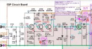
See schematic below... What am I missing/getting wrong?​

Screenshot 2025-09-03 162558.jpg
 
Last edited:
I see what your saying. I think some of my measurments are wrong because I am trying to measure from the component side. when measuring the short legs on the resistors I am not making contact with my probe. I should be measuring from the back side even thought it is harder to determine where the components are.
I remeasured the short leg on r714 on the back side and got -8v.
James
 
I remeasured the short leg on r714 on the back side and got -8v.
OK, R714 short leg is connected to Q716 base and that is -8v.
So now we have a problem with your measurement of R745 because you have 0v on R714 and -8v on R745, but both should be connected together with a trace.​
Unless you have the measured voltages on R745 swapped and you actually measured -8v on the side of R745 that goes to ground?​

Screenshot 2025-09-03 172325.jpg Screenshot 2025-09-03 173738.jpg
​
 
dankik,
I remeasured all the resistors from the back side following your photo with component locations. The R2R was playing in reverse. short leg first.

r715. -8v, 24v
r714. -8, -10v
r745. 0v, -10v
q713. -3v, -3v

Thanks for sending that photo.
James
 
q713. -3v, -3v
I assume that you meant R713 not q713???
I think that you have the voltages for R745 swapped. Take a look at the board diagram below.
You measure the short side of R745 as 0v and long lead side as -10v.
But if you look at the board layout, the long side of R745 (-10v) is tied to the ground trace and should be 0v.
If you had the R745 sides reversed and swapped them, then the 0v side of R745 would be to ground and the -10v side would be connected to the same -10v as R714.
Please check this.

Screenshot 2025-09-04 074927.jpg
 
Here is an adjustment on the ESP Circuit board. I don't know what your output level was, but when you measured the DC voltage at the "checking point" before, you read 22v. I don't know if these two adjustments (R711, R717) will help with the voltages. Do you have a signal generator?

Screenshot 2025-09-04 085737.jpg

Screenshot 2025-09-04 085849.jpg
 
Back
Top Bottom