• The move to the new server is done. There are some software and database maintenance updates in process. This has us passing the hat around to help out. We appreciate any donations. Seriously, even a dollar helps. The payment page may be found here - https://www.audiokarma.org/support.html

Soundcraftsmen PM860 / PCR800 power-amp restoration

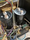
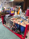
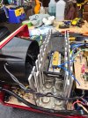
I recapped a PM860 a few months ago. I used Kemet ALS70A series rated for 18k hours at 85C

View attachment 3366170

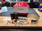
I had to 3D print a spacer to lift the new caps up a bit otherwise the power supply PCB would not clear the transformer windings, and then added a few copper washers to the cap terminals to ensure clearance on the power supply PCB.


View attachment 3366172
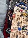
I see a 4136 op amp in the amp, what is the function and can it be upgrade ?
 
There are a couple of them in the regulator circuits. They are not processing audio signals.

I have a Carver C9 from around the same era and it uses a bunch of 4136 opamps. I looked into upgrading to more modern, lower noise parts years ago and found that the 4136 uses a different pinout from almost every other quad op-amp available, even for parts available when the C9 was new. I always suspected they used the 4136 to keep people from easily swapping them out.
 
Last edited:
There are a couple of them in the regulator circuits. They are not processing audio signals.

I have a Carver C9 from around the same era and it uses a bunch of 4136 opamps. I looked into upgrading to more modern, lower noise parts years ago and found that the 4136 uses a different pinout from almost every other quad op-amp available, even for parts available when the C9 was new. I always suspected they used the 4136 to keep people from easily swapping them out.

Is the 860 your best amp so far ?
 
Is the 860 your best amp so far ?
It was good, but I sold it on ebay. I have a Krell KAV300i that I recapped and like a lot, and an Advance Paris A12 (180 W/ch) that I recently bought and like a lot too. I also have a Luxman RX-103 receiver (90 W/ch) that I recapped that sounds pretty good. All of them are good amps, all can drive 4 Ohm loads, all have plenty of power and sound good.
 
Very nicely done!! Can you provide the source for the board at the back that you added on and the value on the Kemet main power caps. I have been putting Nichicon 15,000uf /100v in the ones I have recapped. Love these amps. So quite, warm, powerful and accurate. I use two of them bridged on a set of L200s with an added 2405 tweeter and they sing like angels.
The boards are my design. PM me if you want one. They can be assembled or parts.
I use the kemet caps that are shown in a previous post. I didn't want to put the numbers out there because they already run out often, and are currently out of stock, and not expected for 6 months. My stock won't make it that long. But there's the numbers anyway... guess that's my audio-karma.
The 4136 chips have an odd pin arrangement because they took the power pins positions from the 8 pin chips. It would be a real specific application to need to swap between the two. I guess if there were multiple options on a design and not all sections were needed on the lesser models, then a lower cost option, dual opamp 8 pin IC could be used. Soundcraftsmen used all 4136 opamps except the TL072,82 used in the amp input boards, and some dual opamps in addition to 4136 in the Pro Conrol preamps. My boards use TL084, but it's the common pin-out and anything else could be used. I also designed adapter boards for surface mount to 4136 or 084 pin-out.
 
Last edited:
I recapped a PM860 a few months ago. I used Kemet ALS70A series rated for 18k hours at 85C

View attachment 3366170

I had to 3D print a spacer to lift the new caps up a bit otherwise the power supply PCB would not clear the transformer windings, and then added a few copper washers to the cap terminals to ensure clearance on the power supply PCB.


View attachment 3366172
I have access to a 3D printer and am using NICHICON / LNR2A153MSE, 15,000uf caps. Could you attach the files necessary to produce these?
 
I recapped a PM860 a few months ago. I used Kemet ALS70A series rated for 18k hours at 85C

View attachment 3366170

I had to 3D print a spacer to lift the new caps up a bit otherwise the power supply PCB would not clear the transformer windings, and then added a few copper washers to the cap terminals to ensure clearance on the power supply PCB.


View attachment 3366172
I'd be interested in a copy of the 3D file for the spacer as well, if available!
 
I'd be interested in a copy of the 3D file for the spacer as well, if available!

If you don't want to do the 3D spacer another trick is to go get large Allen set screws the same thread size as the capacitor screws. Get them long enough to put a nut or two beneath the PCB, then another nut with a lock washer on the top side of the PCB. I've done this in several similar circumstances and it works like a champ.
 
I'd be interested in a copy of the 3D file for the spacer as well, if available!
You can download the stl file here: https://drive.google.com/file/d/1Ms9-3Eqf3XDAzkQQtGnKlcMSEgMNkfSr/view?usp=sharing
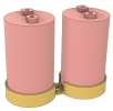
I recommend you print using PETG or ABS. I would not print it with PLA (I wouldn't print anything with PLA). This file is designed specifically for the caps I used and may not fit other caps unless they are the same diameter. It is sized to put the screw terminals in exact alignment with the cap pads on the PCB. The original caps were held down using large steel and fiber washers. You will need to reuse those parts to hold the caps down with this spacer. My intention with the spacer was to be able to put a nut down on the spacer, below the caps, to make everything more stable, but I don't recall if I was able to make that work or not- give it a try. Even without that, it should be more stable than the original design in which the caps were not constrained by anything but the screw terminals.

1736256212898.png

If you don't want to do the 3D spacer another trick is to go get large Allen set screws the same thread size as the capacitor screws. Get them long enough to put a nut or two beneath the PCB, then another nut with a lock washer on the top side of the PCB. I've done this in several similar circumstances and it works like a champ.

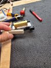
With the specific caps I used, the screw terminal posts are larger than the originals and I was concerned about them shorting traces on the PCB. If you stack things on the cap posts it will be difficult to get the power supply board mounted because whatever you stacked on the cap posts will keep falling off. I soldered three stacked copper washers (5mm ID x 1 mm thick) to the PCB at each cap post. Assembly was super easy.
 
Fantastic, thank you very much! I really appreciate your guidance here. I'll be sure to report back once I have it up and runnning.
 
Be sure to use the original fender washer, fiber washer, and carriage bolt to hold the caps down when you use the printed spacer! The spacer is designed to lift the caps and keeps them from sliding around, but that bolt/nut/washer is needed to hold them down. The screws that go into the cap terminals hold the power supply PCB on the caps.
Don't skip the copper washers soldered to the PCB. They prevent the nut on the cap hold down bolt from shorting against the PCB traces.
 
The 3D printed spacer and 1 mm copper washers worked fantastic in my PM860 rebuild. I did a full re-cap, refreshed the thermal paste on the MOSFETs, and a bunch of other fiddly work... all back together and sounding great. Thank you to mrehorst for making the files available! I tested one channel at a time on a 2 ohm load and the clipping level was around 500 W for short durations.

One question: is there a published DC offset spec for these amps? Mine seems to read about +34 mV on channel A and -11 mV on channel B. I haven't checked the emitter resistor voltages in the prior stages but I'm assuming this is just some modest mismatch in Q1/Q2 on the A channel.

soundcraftsmen cap spacer.jpeg
 
I haven't seen a spec on DC offset. I think it is fixed by CR8, 9, 10, and 11, but I might be wrong. DC bias is adjusted to get 0.4V across R29.
When I finished recapping my amp I had about 10 mV on each channel.

34mV shouldn't be a problem.
 
Good to know, thank you! I may leave well enough alone but may dab some thermal compound between Q1/Q2 and zip tie them together just so they at least track a little closer thermally. I'm pretty impressed with how this thing sounds, and even as someone who used to design SCR drives for a living, I'm amazed at how effective the phase controlled rectifier-based power supply is in keeping up with aggressive load current demand.
 
I did end up replacing Q1 and Q2 on both channels with matched transistors. I added some sleeving to the center leg and mated with thermal compound as described above... here's some reference numbers in case anyone else runs into this in the future. I ordered 100 parts and graded through 50 parts to find the closest matches possible.

Before
Channel A Q1: hFE = 46.9k, Vf = 1.59 V
Channel A, Q2: hFE = 42.1k, Vf = 1.55 V
Channel A dc offset: -11 mV

Channel B Q1: hFE = 59.8k, Vf = 1.59 V
Channel B Q2: hFE = 28.2k, Vf = 1.59 V
Channel B dc offset: +43 mV

After
Channel A, Q1: hFE = 20.8k, Vf = 1.59 V
Channel A, Q2: hFE = 21.0k, Vf = 1.59 V
Channel A dc offset: -10 mV

Channel B Q1: hFE = 21.5k, Vf = 1.59 V
Channel B Q2: hFE = 21.5k, Vf = 1.59 V
Channel B dc offset: -10 mV

 
I did end up replacing Q1 and Q2 on both channels with matched transistors. I added some sleeving to the center leg and mated with thermal compound as described above... here's some reference numbers in case anyone else runs into this in the future. I ordered 100 parts and graded through 50 parts to find the closest matches possible.

Before
Channel A Q1: hFE = 46.9k, Vf = 1.59 V
Channel A, Q2: hFE = 42.1k, Vf = 1.55 V
Channel A dc offset: -11 mV

Channel B Q1: hFE = 59.8k, Vf = 1.59 V
Channel B Q2: hFE = 28.2k, Vf = 1.59 V
Channel B dc offset: +43 mV

After
Channel A, Q1: hFE = 20.8k, Vf = 1.59 V
Channel A, Q2: hFE = 21.0k, Vf = 1.59 V
Channel A dc offset: -10 mV

Channel B Q1: hFE = 21.5k, Vf = 1.59 V
Channel B Q2: hFE = 21.5k, Vf = 1.59 V
Channel B dc offset: -10 mV
Here is an upgrade for the amp

 
That's a really good overview, I don't think he addresses the offset voltage issue though. I did replace the SCRs on the one I worked on and added a little film across the main filter supply caps. Sounds really good!
 
It was an okay overview video. He had some things wrong, and left out a great deal about how the voltages and temperatures control the PCR. It is a clever, linear circuit, only the fan part is a simple on/off control. In fact, I would say he didn't really describe how the PCR worked at all. I didn't catch the part where he described anything about phase, just a description of the SCR portion. He didn't seem to grasp that the voltage is regulated and variable. He talked about the 'soft start' circuit, but did not explain how it actually creates a soft start. Only explained that it's an RC circuit. Also, was incorrect about the function of the zener diodes in the amp circuit. They are there to protect the MOSFET gates from over-voltage. Nothing to do with setting bias voltage. One could also delve into why +/- 70V is chosen as the regulated voltage. There is good electrical design theory there.
 
Last edited:
If you don't want to do the 3D spacer another trick is to go get large Allen set screws the same thread size as the capacitor screws. Get them long enough to put a nut or two beneath the PCB, then another nut with a lock washer on the top side of the PCB. I've done this in several similar circumstances and it works like a champ.
I would only use copper washers as I have shown. The nuts and screws are steel and have a higher electrical and thermal resistance. And the plastic spacer is not necessary with them either. The two washers soldered, gives the proper clearance from the board to transformer.
 
Last edited:
Back
Top Bottom