• The move to the new server is done. There are some software and database maintenance updates in process. This has us passing the hat around to help out. We appreciate any donations. Seriously, even a dollar helps. The payment page may be found here - https://www.audiokarma.org/support.html

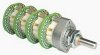
Spec-1 ACV-314 pot lessons learned

a "wild thought" is an avenue to be explored, nothing more.

all those guys are resellers. I'm talking about seeking out the source (probably in China - I've done it before:
my Toyota navigation computer from delco died, and I found the failed board thru aliexpress, and got it going
again after winding through the chain and finding the source - or at least the lowest markup of the same board)


I "did the math" starting from the precision resistance measurements I took (and posted), treated them as independent R2/(R1+R2) voltage dividers and then multiplied the wafers voltage dividers (a*c, b*d) to get
a total attenuation number - and then converted that ratio number into dB. While the results were not as exact as I expected, they WERE close enough to give validity to all my (engineering) expectations and work to date.

My next step would be to get a working Spec-1, feed it a constant signal, get an AC voltmeter that can do Relative db, set the reference at the volume pot's 0 dB position and start checking the other volume pot negative dB positions - to see how closely it follows the front panel markings.

Of course anyone with a spec-1, a constant signal source and a mildly fancy DMM with a Relative dB function can do the same test. You are welcome (and encouraged!!) to post your results in this thread.
I was going to add that if we could locate the linear pot I would buy them for you to conduct your experiment. With the hopes that I might be able to acquire a spare pot for my Spec 1. It is obviously a weak link simply because of age....I'll keep looking...
 
I have a SPEC-1 with a stuck on volume control. I could post up a set of readings if it would help.

YES, Thank You.

You mean the knob won't come off? Have you tried heating the knob? The other alternative (may sound wacky) is to COOL the knob. DRY ICE cool.

regarding the readings: do you have a db reading meter? Or an accurate AC voltmeter that can handle, say, 1 khz?

The procedure would be to measure the output voltage when the volume knob is at zero (ALL the way UP clockwise), then record voltage readings as the volume is successively stepped lower (-2, -4, -6 and so on).
 
No problem! I think I should be able to do that. It might take a week or so to get some time to do it.

I've got a dual AC voltmeter with dB scales (0dB, -10dB -20dB etc) which I think is just fine with 1kHz. Failing that, I also have a Tektronix TDS320 which I regularly use if you'd rather I use that? What voltage would be best to apply at 0dB?

Yes the knob won't come off. I haven't tried heating it yet as its one of the grub screws that is all mushed up :yikes:.
One grub screw came out fairly well but the second just stripped when I tried it get it going. Tried a slightly larger hex and that didn't work. My plan is to use a reverse 2mm drill bit (the kind for screw extracting) and try and either drill the grub screw out or get it to come loose... but I'm open to other suggestions.
 
tap (slight impact, not thread cutting) the 1.5mm allen key into the grub screw and keep up the pressure - the ground up hex can't extend all the way down - hit it with penetrating oil a couple of times over a couple of days.
I also tap with something that bottoms out with out engaging the hexes, to try to loosen the grub screw-aluminum interface.
 
Just one question - is there any way of supporting the aluminium knob to stop the tapping transferring into the pot through the shaft? Maybe just a block of wood underneath just the right height?
 
Nope. The closest thing to do for that is to drill a hole in the center of the face of the knob, then with a puller apply force to the knob, and through that hole to the pot shaft itself.

Still thinking that dry ice thing will contract the metal, actually increasing the diameter of the hole drilled in the aluminum.
IF it does the other thing, and goes into compression, it may have pushed down the proud material on the shaft when the knob equalizes with room temp.
 
Any thoughts on Goldpoint 24 step 4 channel attenuators? They are available with blank wafers you can populate with your own resistors. They're expensive but seem to be very high quality.s-l500.jpg
 
I know of them, the blanks ARE available?

I have gotten various kits and switches for later investigation. I am up to my eyebrows in alligators, otherwise I would have published by now some resistor lists from the kits, they are eye opening.

A most of them rely on the two resistor model for the stepped attenuator. a pair of resistors per step. inputs switched, center points switched as the "slider". common ground.

The spec's is a BUNCH of resistors in a string, ALL energized, and the "slider" is a switch between various resistor junctions.

So if the blanks are available, if they are wired pair switched (which is most likely), it will complicate things. Frankly it would be the equivalent of using 48 multi-turn trimpots.

This is an eBay stepped attenuator kit:
upload_2021-4-13_23-5-58.png
 
Last edited:
I know of them, the blanks ARE available?

I have gotten various kits and switches for later investigation. I am up to my eyebrows in alligators, otherwise I would have published by now some resistor lists from the kits, they are eye opening.

A most of them rely on the two resistor model for the stepped attenuator. a pair of resistors per step. inputs switched, center points switched as the "slider". common ground.

The spec's is a BUNCH of resistors in a string, ALL energized, and the "slider" is a switch between various resistor junctions.

So if the blanks are available, if they are wired pair switched (which is most likely), it will complicate things. Frankly it would be the equivalent of using 48 multi-turn trimpots.

View attachment 2194079
The website states that the wafer resistors are wired in series. They don't show (or I haven't found) an image of the trace side of a wafer. I took a gamble and ordered a 4 channel switch with 2 of their standard log taper wafers in front and 2 blank wafers in the rear. AND an additional 2 blank wafers just in case the standard log tapers are not good enough. $278 with shipping and tax. I will post some detailed pics when it gets here for commentary.
 
I know of them, the blanks ARE available?

I have gotten various kits and switches for later investigation. I am up to my eyebrows in alligators, otherwise I would have published by now some resistor lists from the kits, they are eye opening.

A most of them rely on the two resistor model for the stepped attenuator. a pair of resistors per step. inputs switched, center points switched as the "slider". common ground.

The spec's is a BUNCH of resistors in a string, ALL energized, and the "slider" is a switch between various resistor junctions.

So if the blanks are available, if they are wired pair switched (which is most likely), it will complicate things. Frankly it would be the equivalent of using 48 multi-turn trimpots.

View attachment 2194079
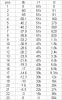
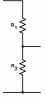
In this chart, what do r1 and r2 represent specifically?
 
The website states that the wafer resistors are wired in series. They don't show (or I haven't found) an image of the trace side of a wafer. I took a gamble and ordered a 4 channel switch with 2 of their standard log taper wafers in front and 2 blank wafers in the rear. AND an additional 2 blank wafers just in case the standard log tapers are not good enough. $278 with shipping and tax. I will post some detailed pics when it gets here for commentary.

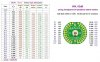
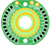
The switch is not here yet but I found an image of the trace side of the log wafer....unnamed.png
 
In this chart, what do r1 and r2 represent specifically?

The chart was a chinese kit's list of resistors. 2 resistors per step per channel. NOTHING to do with ANY Spec-1 pot wafer. Schematic's are radically different.
ALL Spec-1 resistors are always carrying signal, while the chinese kit only 2 resistors of the 24 or 26 are carrying signal.

upload_2021-4-16_0-28-37.png

----------------------------------------------------------------------------------------------------------------------------

The best information about the spec-1 resistances on each wafer is on post 27, on February 7, 2021
Each pair of readings done from OUTSIDE of the pot, using the parlance of the above posts,
say at step 7 , is a "R1" resistance reading of
R1 + R2 + R3 + R4 + R5 + R6 +R7
and a second resistance "R2" reading of
R8 + R9 + R10 + R11 + R12+ R13+ R14+ R15+ R16+ R17+ R18+ R19+ R20+ R21+ R22+ R23

step 9 is:\
is a "R1" resistance reading of
R1 + R2 + R3 + R4 + R5 + R6 +R7 + R8 + R9
and a second resistance "R2" reading of
R10 + R11 + R12+ R13+ R14+ R15+ R16+ R17+ R18+ R19+ R20+ R21+ R22+ R23

Thus each reading PAIR will total to the full end to end resistance of the "pot".
more examples:

Step 2 is:
is a "R1" resistance reading of
R1 + R2
and a second resistance "R2" reading of
R3 + R4 + R5 + R6 +R7 + R8 + R9 + R10 + R11 + R12+ R13+ R14+ R15+ R16+ R17+ R18+ R19+ R20+ R21+ R22+ R23

step 22 is:
is a "R1" resistance reading of
R1 + R2 + R3 + R4 + R5 + R6 +R7 + R8 + R9 + R10 + R11 + R12+ R13+ R14+ R15+ R16+ R17+ R18+ R19+ R20+ R21
and a second resistance "R2" reading of
R22+ R23

You get the idea.
I have NOT gone through these examples for absolute accuracy, they were to impart an idea.

 
Last edited:
Goldpoint resistor layout04162021_00000.jpg
The chart was a chinese kit's list of resistors. 2 resistors per step per channel. NOTHING to do with ANY Spec-1 pot wafer. Schematic's are radically different.
ALL Spec-1 resistors are always carrying signal, while the chinese kit only 2 resistors of the 24 or 26 are carrying signal.

View attachment 2196165

----------------------------------------------------------------------------------------------------------------------------

The best information about the spec-1 resistances on each wafer is on post 27, on February 7, 2021
Each pair of readings done from OUTSIDE of the pot, using the parlance of the above posts,
say at step 7 , is a "R1" resistance reading of
R1 + R2 + R3 + R4 + R5 + R6 +R7
and a second resistance "R2" reading of
R8 + R9 + R10 + R11 + R12+ R13+ R14+ R15+ R16+ R17+ R18+ R19+ R20+ R21+ R22+ R23

step 9 is:\
is a "R1" resistance reading of
R1 + R2 + R3 + R4 + R5 + R6 +R7 + R8 + R9
and a second resistance "R2" reading of
R10 + R11 + R12+ R13+ R14+ R15+ R16+ R17+ R18+ R19+ R20+ R21+ R22+ R23

Thus each reading PAIR will total to the full end to end resistance of the "pot".
more examples:

Step 2 is:
is a "R1" resistance reading of
R1 + R2
and a second resistance "R2" reading of
R3 + R4 + R5 + R6 +R7 + R8 + R9 + R10 + R11 + R12+ R13+ R14+ R15+ R16+ R17+ R18+ R19+ R20+ R21+ R22+ R23

step 22 is:
is a "R1" resistance reading of
R1 + R2 + R3 + R4 + R5 + R6 +R7 + R8 + R9 + R10 + R11 + R12+ R13+ R14+ R15+ R16+ R17+ R18+ R19+ R20+ R21
and a second resistance "R2" reading of
R22+ R23

You get the idea.
I have NOT gone through these examples for absolute accuracy, they were to impart an idea.
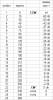
For your perusal please.....I'm trying to get ahead of the game before the switch gets here. Here is my understanding of how the Goldpoint switch could be made to work. I'm using your resistor values and at the positions of 0.0 I have jumpers. The Goldpoint has two extra positions and I put those at the top end. I know the panel markings will not be correct but that might be a necessary casualty of this replacement. What do you think?
 
Last edited:
edit: was perusing labels etc and found out I was doing it bass ackwards....

Nice work. That was my conception a while back. The switch positions are most likely 15 degrees each, so I started all the way CCW as infinite, and 1 step up as -60. the extra position(s?) will be unmarked on the panel but wired as no attenuation - and will usually not be noticed - who goes fully CW on a volume control? (lol)

Some of the mashing is to come up with a "perfect" by the numbers reference line - remember that each individual wafer and resistance is DIFFERENT because of the laser trimming, so I was trying to use the panel label db numbers to correct the real readings to the theoretical target number, and in a series string each resistor's error is real and can be used to hit the average ideal line. Part of what could be done with laser trimming and recalculation, to get that 0.2db gang error and 0.2 db step error.


sorry you had to calculate all that I just haven't been able to keep up, and pull pages from the spreadsheet I have been mashing numbers in.

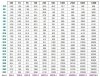
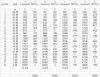
some old mashed numbers:

upload_2021-4-22_3-17-55.png

LOTS of spreadsheet mashing... not made for the public, sometimes I barely remember why for some failed brain farts...
 
Last edited:
edit: was perusing labels etc and found out I was doing it bass ackwards....

Nice work. That was my conception a while back. The switch positions are most likely 15 degrees each, so I started all the way CCW as infinite, and 1 step up as -60. the extra position(s?) will be unmarked on the panel but wired as no attenuation - and will usually not be noticed - who goes fully CW on a volume control? (lol)

Some of the mashing is to come up with a "perfect" by the numbers reference line - remember that each individual wafer and resistance is DIFFERENT because of the laser trimming, so I was trying to use the panel label db numbers to correct the real readings to the theoretical target number, and in a series string each resistor's error is real and can be used to hit the average ideal line. Part of what could be done with laser trimming and recalculation, to get that 0.2db gang error and 0.2 db step error.


sorry you had to calculate all that I just haven't been able to keep up, and pull pages from the spreadsheet I have been mashing numbers in.

some old mashed numbers:

View attachment 2196884

LOTS of spreadsheet mashing... not made for the public, sometimes I barely remember why for some failed brain farts...

View attachment 2196896
No apology necessary. Your work on this and so many other things is priceless. I can't help being fascinated by the uniqueness of the Spec 1. However, I have learned that at least one other preamp has used a 4 channel attenuator with combo log/linear tapers...the Mcintosh C20 tube preamp.
 
Last edited:
I have learned that at least one other preamp has used a 4 channel attenuator with combo log/linear tapers...the Mcintosh C20 tube preamp.

The SA-9900 also uses a 4-section step attenuator (ACV-315) in a similar configuration as the SPEC-1 although I'm not sure if it has both log and linear tapers.

ACV-315.JPG
 
Back
Top Bottom