

You are using an out of date browser. It may not display this or other websites correctly.
You should upgrade or use an alternative browser.
You should upgrade or use an alternative browser.
Spec-1 ACV-314 pot lessons learned
- Thread starter markthefixer
- Start date


Here is the switch installed. I removed the front plate to enlarge the mounting hole to make sure no metal filings got into the interior. A small Dremel grinding attachment was all I needed. The stock switch can still be reinstalled if I want. I will be putting it back in my system this weekend to do some testing. However, I just have to mention that my 2238 makes a damn nice preamp too.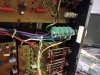

nevermind? Checking...
Double check that wiring, put the switch into the INF step. You should get 0 ohms TO that wafer's ground on all 4 wafers on the moving contact.
Double checked my "unmolested Spec-1" and the grounds are in the correct place.
Did you notice that wafer c & d wafer grounds are tied together, and a long black wire goes to the regulated supply star ground.
Wafers A & B ONLY catch the ground on the shielded cables.
Double check that wiring, put the switch into the INF step. You should get 0 ohms TO that wafer's ground on all 4 wafers on the moving contact.
Double checked my "unmolested Spec-1" and the grounds are in the correct place.
Did you notice that wafer c & d wafer grounds are tied together, and a long black wire goes to the regulated supply star ground.
Wafers A & B ONLY catch the ground on the shielded cables.
Last edited:
Yes that is what I get. I actually now consider that to be position "0" and didn't include it in my chart. I will correct that. What do you think about the rest? Did you see my question about shielding?nevermind? Checking...
Double check that wiring, put the switch into the INF step. You should get 0 ohms TO that wafer's ground on all 4 wafers on the moving contact.
Shielding is a tricky question.
There ARE shields in the ACV-314. Metal sheets between each wafer. Disc staked to the end of the shaft behind wafer D. All tied with the screws running through the body of the pot.
Talk to Goldpoint?
There ARE shields in the ACV-314. Metal sheets between each wafer. Disc staked to the end of the shaft behind wafer D. All tied with the screws running through the body of the pot.
Talk to Goldpoint?
No I haven't asked Goldpoint. But I do have one of those DIY switches and I have to say...they ain't no better?Shielding is a tricky question.
There ARE shields in the ACV-314. Metal sheets between each wafer. Disc staked to the end of the shaft behind wafer D. All tied with the screws running through the body of the pot.
Talk to Goldpoint?
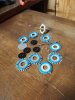
Here's the DIY switch I purchased before....No I haven't asked Goldpoint. But I do have one of those DIY switches and I have to say...they ain't no better?
Yes I have c and d grounds tied together and that long black wire is connected as original. I connected the cables exactly as original as related to input, output, and ground.nevermind? Checking...
Double check that wiring, put the switch into the INF step. You should get 0 ohms TO that wafer's ground on all 4 wafers on the moving contact.
Double checked my "unmolested Spec-1" and the grounds are in the correct place.
Did you notice that wafer c & d wafer grounds are tied together, and a long black wire goes to the regulated supply star ground.
Wafers A & B ONLY catch the ground on the shielded cables.
My Spec 1 was "unmolested" until I removed the switch for this experiment. That's ok though since I'll never sell it.nevermind? Checking...
Double check that wiring, put the switch into the INF step. You should get 0 ohms TO that wafer's ground on all 4 wafers on the moving contact.
Double checked my "unmolested Spec-1" and the grounds are in the correct place.
Did you notice that wafer c & d wafer grounds are tied together, and a long black wire goes to the regulated supply star ground.
Wafers A & B ONLY catch the ground on the shielded cables.
Sadly, the Spec-1 I refer to had some unspeakable stuff (stupid stuff) done to it, that I am reversing. It also had the busted volume control.
Last edited:

@rhodus do you have or do you know anyone who has equipment that would allow you to run a bode plot on your modified SPEC1?
Why I'm asking: https://audiokarma.org/forums/index.php?threads/spec-1-frequency-response-guidance-required.652054
Why I'm asking: https://audiokarma.org/forums/index.php?threads/spec-1-frequency-response-guidance-required.652054
@rhodus do you have or do you know anyone who has equipment that would allow you to run a bode plot on your modified SPEC1?
Why I'm asking: https://audiokarma.org/forums/index.php?threads/spec-1-frequency-response-guidance-required.652054
I do not have that equipment and I'm in a Vintage Tech Desert here in Baton Rouge. The only repair shops here pretty much only replace circuit boards in flat screen TVs. Do you think Mark's switch idea could be a solution to the issue? I read the whole thread you referred to and it really changed the way I see my Spec1. If there are any tests I could do with my basic equipment just let me know. I do have a scope but only limited knowledge of how to use it.
Well I hope I didn't spoil your appreciation of the SPEC1. Even with the frequency response issues, I'm sure our ears can't actually hear the difference. I'm just interested in finding out if your replacement amplitude switch changed the frequency response. You could do the test with a scope but you would need a signal generator that can produce a sine wave of a consistent amplitude from 20Hz to at least 70kHz. Most laptops with signal generator software can't do this.
I would like to see those test results performed on other preamps, the 1250, Marantz, Sansui, McIntosh, etc.....Well I hope I didn't spoil your appreciation of the SPEC1. Even with the frequency response issues, I'm sure our ears can't actually hear the difference. I'm just interested in finding out if your replacement amplitude switch changed the frequency response. You could do the test with a scope but you would need a signal generator that can produce a sine wave of a consistent amplitude from 20Hz to at least 70kHz. Most laptops with signal generator software can't do this.
Well I hope I didn't spoil your appreciation of the SPEC1. Even with the frequency response issues, I'm sure our ears can't actually hear the difference. I'm just interested in finding out if your replacement amplitude switch changed the frequency response. You could do the test with a scope but you would need a signal generator that can produce a sine wave of a consistent amplitude from 20Hz to at least 70kHz. Most laptops with signal generator software can't do this.
It WON'T xlbee. It is so close to the original, the only variations would be the same ones as found unit to unit. (be it a Spec-1 or just the ACV-314 that you define as the "unit").
It WILL present the same loads incoming and outgoing.
TL/DR, this is what it's about:
I noticed the output of my SPEC 1 (recapped last winter) was about .5 dB down at about 20 kHz and trailed off from there. According to the specs, it isn't supposed to be .5 dB down until about 70 kHz.
The response of preamps is always measured with the volume control at max.
You have your order mixed up a little.
The order is Tone, Filter, Buffer stages. The volume control is a double ganged four element unit and the volume control is before the tone and an in between the filter and buffer stages. The balance control is between the tone and filter stages.
I would expect you are seeing normal behaviour, as the filter assembly would be loaded down by the volume control at its low level settings.
That said, I agree with you that a frequency response should be the same across all volume settings. Sadly, this is rarely the case and the primary reason frequency response is pretty much always measured at volume max. The same happens with input level controls on power amps- they affect the HF response as soon as you pad them down in level.

Mark, you are probably right but maybe the way the resistors are printed on the SPEC 1 switch wafers cause more capacitance (and thus high frequency roll-off) than a through hole carbon film resistor? Besides testing stuff is fun!
Realistically,
Maybe at hundreds of Megahertz, more like sub-Gigahertz speeds.
It is the resistance of the switch position's effect upon the subsequent stage.
Put a buffer amp between the two of them to decouple the effect (and add to the noise floor as well as other effects), it has been done in some of the receivers
- just not for that specific reason. SX-950, SX-1250 just off the top of my head, between the balance control and the volume control. But NOT on the SX-1280 & SX-1980.
Testing stuff is fun? OK ... you have a road map in this thread, a resistor parts list that is easily copied and ordered through mouser - about 18 bucks plus shipping - which will do 5 controls.
as for switches:
eBay item # 254284802957 about 18 bucks
eBay item #/254786864646 kit for a log-a attenuator (I was not impressed!!) about 28 bucks (for the switch)
Build your own and test to your heart's content. Probably for less than 50 bucks...
MAYBE after I can build and test one in a spec-1 here (that I have a REAL ACV-314 to put in it) I can LEND you the one I will build.
Then you can swap it in, and exorcise that demon.
Right now, I'm NOT having fun - maybe I'm going through a stick-in-the -mud phase but I'm starting to feel distracted.
MY thoughts on the matter are it's like pole vaulting over mouse poop, the poop exists but it is still overreaction.
This may be one of the posts where I end up apologizing, at least this time I realize my motivation is based on emotion versus tech, when I offend someone.


Realistically,
Maybe at hundreds of Megahertz, more like sub-Gigahertz speeds.
It is the resistance of the switch position's effect upon the subsequent stage.
Put a buffer amp between the two of them to decouple the effect (and add to the noise floor as well as other effects), it has been done in some of the receivers
- just not for that specific reason. SX-950, SX-1250 just off the top of my head, between the balance control and the volume control. But NOT on the SX-1280 & SX-1980.
Testing stuff is fun? OK ... you have a road map in this thread, a resistor parts list that is easily copied and ordered through mouser - about 18 bucks plus shipping - which will do 5 controls.
as for switches:
eBay item # 254284802957 about 18 bucks
eBay item #/254786864646 kit for a log-a attenuator (I was not impressed!!) about 28 bucks (for the switch)
Build your own and test to your heart's content. Probably for less than 50 bucks...
MAYBE after I can build and test one in a spec-1 here (that I have a REAL ACV-314 to put in it) I can LEND you the one I will build.
Then you can swap it in, and exorcise that demon.
Right now, I'm NOT having fun - maybe I'm going through a stick-in-the -mud phase but I'm starting to feel distracted.
MY thoughts on the matter are it's like pole vaulting over mouse poop, the poop exists but it is still overreaction.
This may be one of the posts where I end up apologizing, at least this time I realize my motivation is based on emotion versus tech, when I offend someone.
Ah now there's the Mark we know and love! Let it out brother! No need to apologize. For me, electronics is a lot of fun. That's why I wanted to be an electronic technician and fix stuff until I realized it's pretty tough making ends meet with that as a career. So now it's just a fun hobby. This winter I spent weeks learning how to do a complete alignment on a TX-9500II, just for fun (turned out great too btw). Anyway, I sold my SPEC1 in favor of an Exclusive C3a so can't really go down that road at the moment. Back to our regularly scheduled program.
I'm happy to report that the switch works. Dead silent at position "0" and seamless all the way to 2 o'clock where I would have to leave the room to go any higher. Guess I'm not getting the full 70khz.....
It feels very nice and is clean as can be. No static at all. I'm gonna leave it in and keep the ACV 314 on hand.
It feels very nice and is clean as can be. No static at all. I'm gonna leave it in and keep the ACV 314 on hand.