• The move to the new server is done. There are some software and database maintenance updates in process. This has us passing the hat around to help out. We appreciate any donations. Seriously, even a dollar helps. The payment page may be found here - https://www.audiokarma.org/support.html

Spec-1 ACV-314 pot lessons learned

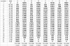
What I meant was that the resistance measured and calculated A B C D are probably backwards. Gotta think it through, what I did etc in what order, in order to extract.

You see, position 1 should be inf, position 2 should be -60 db, position 3 should be -50 db .....
position 22 should be 0 db, while superfluous position 23 should also be 0 db.

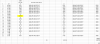
upload_2021-4-22_1-26-28.png

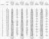
And by using subtraction to expose each resistor in the string:

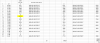
upload_2021-4-22_1-35-21.png
 
Last edited:
What I meant was that the resistance measured and calculated A B C D are probably backwards. Gotta think it through, what I did etc in what order, in order to extract.

You see, position 1 should be inf, position 2 should be -60 db, position 3 should be -50 db .....
position 22 should be 0 db, while superfluous position 23 should also be 0 db.

View attachment 2199446

Thus calculated:
View attachment 2199453
Got it. Before I install any resistors I will take measurements from my own working switch and compare to yours.
 
well, I do think that last table got it right. Now to match up the needed resistances with standard values.

now, these are NOT chip resistors, they are thru-hole leaded resistors.

edit: these tables had been reversed, rhodus's 4-19-2012 10:19 pm post called attention
to a glaring mistake. These tables have been fixed.

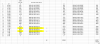
upload_2021-4-22_3-9-28.png

upload_2021-4-22_3-9-49.png

upload_2021-4-22_3-10-22.png

upload_2021-4-22_3-10-56.png


Now, as for the accuracy, there is a NUMERIC comparison between what is required at the position and what the value of the part is. It can be meaningless because there is the 1% tolerance difference in the resistors from their paper value and their real tolerance influenced value. For example the 505 ohm resistor can range between 500 and 510 ohms and still be within the 1% tolerance

even so, the differences between the sum of the readings and the sum of the standard parts values is:
a 42 ohms (out of approx 50k ohms)
b -14 ohms (out of approx 50k ohms)
c -50 ohms (out of approx 50k ohms)
d 33 ohms (out of approx 50k ohms)
(BTW +/- 1% of 50,000 ohms is 50,500 and 49,500) I'm not sure where the db's line up (yet).

Looks close enough to me where I would spend money on the resistors to test with some of the switches I have at home..
BTW, each of those is 0.23 each for THROUGH HOLE resistors.
 
Last edited:
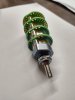
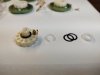
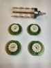
The switch arrived today and it reeks of quality. The first thing to do was remove the wafers and transfer the sliding mechanisms from the 2 standard wafers to the 2 extra blank wafers I ordered. Very easy to do but had to be careful because the spring loaded slider contact will pop out. I could have avoided this step and saved $35 by ordering all blank wafers. This 4 channel switch with all blank wafers is $199 + tax and shipping. Oh yea, you have to get your own resistors too. I have the wafers ready to populate so now its time to get those resistors......IMG_20210419_122427626_HDR.jpg IMG_20210419_122455015.jpg IMG_20210419_122557504.jpg IMG_20210419_122707280_HDR.jpg IMG_20210419_123729044.jpg IMG_20210419_124112420.jpg IMG_20210419_125531798_HDR.jpg IMG_20210419_125551141_HDR.jpg IMG_20210419_130656557_HDR.jpg
 

Attachments

  • IMG_20210502_144240030.jpg
    IMG_20210502_144240030.jpg
    76.4 KB · Views: 7
Last edited:
well, I do think that last table got it right. Now to match up the needed resistances with standard values.

now, these are NOT chip resistors, they are thru-hole leaded resistors.

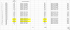
View attachment 2200425

View attachment 2200426

View attachment 2200427

View attachment 2200428

Now, as for the accuracy, there is a NUMERIC comparison between what is required at the position and what the value of the part is. It can be meaningless because there is the 1% tolerance difference in the resistors from their paper value and their real tolerance influenced value. For example the 505 ohm resistor can range between 500 and 510 ohms and still be within the 1% tolerance

even so, the differences between the sum of the readings and the sum of the standard parts values is:
a 42 ohms (out of approx 50k ohms)
b -14 ohms (out of approx 50k ohms)
c 10 ohms (out of approx 50k ohms)
d 33 ohms (out of approx 50k ohms)
(BTW +/- 1% of 50,000 ohms is 50,500 and 49,500) I'm not sure where the db's line up (yet).

Looks close enough to me where I would spend money on the resistors to test with some of the switches I have at home..
BTW, each of those is 0.23 each for THROUGH HOLE resistors.
The Goldpoint blank wafers are intended for thru hole resistors. They recommend KOA Speer brand?
 
No recommendation, just what is stocked by Mouser.

Of course the 0's are jumper wires.

well, I do think that last table got it right. Now to match up the needed resistances with standard values.

now, these are NOT chip resistors, they are thru-hole leaded resistors.

View attachment 2200425

View attachment 2200426

View attachment 2200427

View attachment 2200428

Now, as for the accuracy, there is a NUMERIC comparison between what is required at the position and what the value of the part is. It can be meaningless because there is the 1% tolerance difference in the resistors from their paper value and their real tolerance influenced value. For example the 505 ohm resistor can range between 500 and 510 ohms and still be within the 1% tolerance

even so, the differences between the sum of the readings and the sum of the standard parts values is:
a 42 ohms (out of approx 50k ohms)
b -14 ohms (out of approx 50k ohms)
c 10 ohms (out of approx 50k ohms)
d 33 ohms (out of approx 50k ohms)
(BTW +/- 1% of 50,000 ohms is 50,500 and 49,500) I'm not sure where the db's line up (yet).

Looks close enough to me where I would spend money on the resistors to test with some of the switches I have at home..
BTW, each of those is 0.23 each for THROUGH HOLE resistors.
I think the resistance values in these charts are inverted as related to position number and db markings. For instance, on wafer "A", if position "1" is infinite db or zero ohms, shouldn't position #2 be 500 ohms? Position #3 be 600 ohms, and so on? I'm pretty sure that's the way I'm measuring it on my Spec. All my values are matching yours very closely, well within 1%.
 
Yes, you are correct. I have and will continue to go back and fix the postings. I have figured a quick and slick way to reverse the lists.

My in-circuit spec readings of wafer A are sticking around 5 kilo ohms, thus in circuit readings are not accurate.
Continuing to investigate...
One salient fact, in the unit, the 3 terminals on each pot wafer point DOWN, putting the ground (black wires) on the fully CCW end.
(to the left - I think I had that backwards, cuz rotate 180 degrees to SEE it, puts the ground on the right, then I forgot to make the correction.)

Also the business side of the wafer faces AWAY from the front panel!!
Parts dump:

upload_2021-4-22_4-54-51.png


and text:

A.2 -60 dB 502 660-MF1/4DC5050F
B.2 -60 dB 501 660-MF1/4DC5050F
A.3 -50 dB 629 660-MF1/4DCT52R6340F
B.3 -50 dB 630 660-MF1/4DCT52R6340F
A.6 -33 dB 874 660-MF1/4DC8870F
B.6 -33 dB 876 660-MF1/4DC8870F
A.4 -42 dB 904 660-MF1/4DC9090F
B.4 -42 dB 901 660-MF1/4DC9090F
A.11 -22 dB 1093 660-MF1/4DC1101F
B.11 -22 dB 1098 660-MF1/4DC1101F
A.7 -30 dB 1122 660-MF1/4DC1131F
B.7 -30 dB 1122 660-MF1/4DC1131F
A.5 -37 dB 1226 660-MF1/4DC1241F
B.5 -37 dB 1231 660-MF1/4DC1241F
C.5 -37 dB 1405 660-MF1/4DC1401F
D.5 -37 dB 1409 660-MF1/4DC1401F
A.8 -28 dB 1518 660-MF1/4DC1501F
B.8 -28 dB 1518 660-MF1/4DC1501F
A.13 -18 dB 1582 660-MF1/4DC1581F
B.13 -18 dB 1587 660-MF1/4DC1581F
A.10 -24 dB 1777 660-MF1/4DC1781F
B.10 -24 dB 1779 660-MF1/4DC1781F
C.7 -30 dB 2022 660-MF1/4DC2001F
D.7 -30 dB 2017 660-MF1/4DC2001F
C.3 -50 dB 2278 660-MF1/4DC2261F
D.3 -50 dB 2279 660-MF1/4DC2261F
A.12 -20 dB 2639 660-MF1/4DC2671F
B.12 -20 dB 2637 660-MF1/4DC2671F
C.11 -22 dB 2780 660-MF1/4DC2741F
D.11 -22 dB 2760 660-MF1/4DC2741F
B.17 -10 dB 2750 660-MF1/4DC2741F
A.17 -10 dB 2797 660-MF1/4DC2801F
C.13 -18 dB 3042 660-MF1/4DC3091F
D.13 -18 dB 3034 660-MF1/4DC3091F
C.4 -42 dB 3302 660-MF1/4DC3321F
D.4 -42 dB 3306 660-MF1/4DC3321F
C.6 -33 dB 3392 660-MF1/4DC3401F
D.6 -33 dB 3392 660-MF1/4DC3401F
B.19 -6 dB 3620 660-MF1/4DC3601F
C.17 -10 dB 3654 660-MF1/4DC3651F
D.17 -10 dB 3665 660-MF1/4DC3651F
A.19 -6 dB 3672 660-MF1/4DC3651F
C.19 -6 dB 3769 660-MF1/4DC3741F
D.19 -6 dB 3775 660-MF1/4DC3741F
A.14 -16 dB 3807 660-MF1/4DC3831F
B.14 -16 dB 3813 660-MF1/4DC3831F
A.16 -12 dB 4774 660-MF1/4DC4751F
B.16 -12 dB 4755 660-MF1/4DC4751F
C.9 -26 dB 4758 660-MF1/4DC4751F
D.9 -26 dB 4729 660-MF1/4DC4751F
C.2 -60 dB 5231 660-MF1/4DC5231F
D.2 -60 dB 5221 660-MF1/4DC5231F
A.18 -8 dB 6279 660-MF1/4DC6341F
B.18 -8 dB 6299 660-MF1/4DC6341F
C.15 -14 dB 6770 660-MF1/4DC6801F
D.15 -14 dB 6730 660-MF1/4DC6801F
A.20 -4 dB 7355 660-MF1/4DC7321F
B.20 -4 dB 7357 660-MF1/4DC7321F
A.21 -2 dB 7705 660-MF1/4DC7681F
B.21 -2 dB 7727 660-MF1/4DC7681F
C.22 0 dB 7707 660-MF1/4DC7681F
D.22 0 dB 7710 660-MF1/4DC7681F


BOM

660-MF1/4DC5050F|10
660-MF1/4DCT52R6340F|10
660-MF1/4DC8870F|10
660-MF1/4DC9090F|10
660-MF1/4DC1101F|10
660-MF1/4DC1131F|10
660-MF1/4DC1241F|10
660-MF1/4DC1401F|10
660-MF1/4DC1501F|10
660-MF1/4DC1581F|10
660-MF1/4DC1781F|10
660-MF1/4DC2001F|10
660-MF1/4DC2261F|10
660-MF1/4DC2671F|10
660-MF1/4DC2741F|20
660-MF1/4DC2801F|10
660-MF1/4DC3091F|10
660-MF1/4DC3321F|10
660-MF1/4DC3401F|10
660-MF1/4DC3601F|10
660-MF1/4DC3651F|20
660-MF1/4DC3741F|10
660-MF1/4DC3831F|10
660-MF1/4DC4751F|20
660-MF1/4DC5231F|10
660-MF1/4DC6341F|10
660-MF1/4DC6801F|10
660-MF1/4DC7321F|10
660-MF1/4DC7681F|20


edit 626 ohm (-3) on backorder, using 634 for a 629 target (+5)

 
Last edited:
Bump for all the edits and table changes.

Resistors ordered from Mouser.

The pricing of the resistors was $0.23 ea in 1 - 9 quantities, and all values required at least two for $0.46
while 10 of them was $0.55, just 9 cents more. Thus the bump to 10 for the quantity.


660-MF1/4DC6260F the only 626 ohm resistor is this non-stocked one, the next stocked resistance after 626 ohms is 634 ohms, our originals are 629 and 630 ohms.

660-MF1/4DC6260F
vs.
660-MF1/4DCT52R6340F
this part number is same temp comp ratio (D:100ppm), termination material (C:SnCu) & tolerance (F:1%)
the T52R is T52:tape packaged on a R:reel ( as opposed to A: ammo - folded belt) with no lead forming, so the other resistor numbers are just loose (bulk) resistors..
 
Last edited:
IMG_20210501_183255064.jpg I've been busy with HVAC service lately and haven't taken the time to do some measurements on my own Spec 1 pot but here it is. This is a fully working unit that I removed for testing. It does sometimes have very very faint static pops in the lower scale (the most worn portion I guess) when moving from position to position, but nothing to concern me. I will install the Goldpoint pot at some point to hear how it works and see if this experiment is a success....Comments welcome...IMG_20210501_152820792_HDR.jpgIMG_20210501_152852648.jpg
I want to add that my understanding of the Spec pot terminals is this: Looking at the switch from the shaft end, terminals facing up, the far right terminals are the grounds, center terminals slider out, left terminals input. They are not marked on the pot.
 
Last edited:
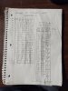
Comparing Mark's resistor list to mine. The circled values are where Mark showed two different a/b resistors for those positions. I chose the values that most closely matches my readings. Now to make an order. I'll be back once they get here....IMG_20210502_142132751.jpg

Order placed....probably the cheapest Mouser order I've made...$18.15 + $7.99 shipping...
 
Last edited:
OK, I finally did something I have wanted to do for a long time.

I put a 1khz, 100 mVolt AC signal into a working Spec-1 I have here, A completely INTACT unit with it's ORIGINAL volume control. PROBABLY an Echowars unit.

I then dialed up the Spec-1 to 0 dB; full output and set it as the meter's 0 dB point for the meter's dB calculations.
Then I started dialing down the labelled steps on the Spec-1's volume control; -2 dB , -4 dB and etc...

The ONLY reading that wasn't completely bang on was the -50 dB step, IT read -49.97 dB.
Everything else was darn near perfect.
But remember, this is the reference unit - NOT the replacement control (as yet unbuilt).

Then I started to take a good look in the Spec-1 unit that had the destroyed volume control, that I have been reengineering the replacement for.

I was brought up short, a bunch of shielded cables NOT involved with the volume control were hanging loose, disconnected/unwrapped. Then I noticed disconnected power lines
and disconnected grounds :yikes: :wtf:.

Needless to say, a lot needs to be done before I can hook up the project volume control and pass a signal through at least those sections. :(

Glad I saw that before I tried to squeeze in time to actually build a switched attenuator like the ACV-314 to run through tests. To validate all this work.

Sigh... I have everything to start now, except a live circuit to install it in: resistors (enough for FIVE!!!), several switches, multitude of ideas for assembly, etc...
 
Last edited:
Nevermind, at least once you're done assembling it, you'll know that everything really is good and solid for the volume control tests. I haven't forgotten about the testing of the SPEC-1 volume. I'm just struggling to get time to do it. I'll still do it and post results if its still of use.
 
Nevermind, at least once you're done assembling it, you'll know that everything really is good and solid for the volume control tests. I haven't forgotten about the testing of the SPEC-1 volume. I'm just struggling to get time to do it. I'll still do it and post results if its still of use.

No, Thank You, it's done. My previous post was the first unmolested spec-1

I did the second unmolested Spec-1 this morning, and the numbers were spot on, very accurate considering on the pot it is printed with +/- 0.2db step error and 0.2db gang error.

Basically, they reflected the panel labels: -2.00xxx dB, -4.00xxx dB and so, with -50 db on this one -50.0xxx dB.

The third Spec-1 waits for me to fix it's molestation, build the control and install it.
 
Last edited:
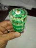
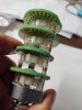
Here is my assembled switch and first test results. The mounting shaft of this switch is a tiny bit larger than stock so the mounting hole in the panel would have to be slightly enlarged for this switch. And I'm pretty sure the steps will not perfectly align with the panel markings. Otherwise, as far as the tracking goes, it seems this could work?IMG_20210518_202016075.jpgIMG_20210518_204024750.jpg
 
Question about shielding...the conductors that connect to the Spec switch are shielded. The Spec switch is in a plastic case and is not shielded. Likewise, this switch is wide open not shielded. Is that a concern?
 
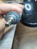
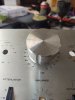
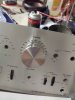
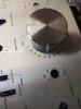
GREAT DEVELOPMENT!! I temp installed the switch on the faceplate (no enlarging required) to check the step angles and they are the same! The difference is the Goldpoint switch travels farther around, one step before returning to infinite. So, the only difference is there are two extra blank steps past 0db. All the other steps line up! IMG_20210519_123542446.jpg 16214448553611630775781390665645.jpg
 

Attachments

  • IMG_20210519_123616117.jpg
    IMG_20210519_123616117.jpg
    63.3 KB · Views: 5
  • IMG_20210519_123602259.jpg
    IMG_20210519_123602259.jpg
    83.2 KB · Views: 5
Last edited:
Also, I suspect that a pin can be installed in the step mechanism to prevent it from traveling past 0db. Gonna get in touch with Goldpoint on that.
 
Just got the answer from Goldpoint. Spectacular service!
goldpoint stop pins.gif

They are mailing me a second stop screw free of charge. If I had known I could have ordered it with the switch.
 
Last edited:
Back
Top Bottom