

You are using an out of date browser. It may not display this or other websites correctly.
You should upgrade or use an alternative browser.
You should upgrade or use an alternative browser.
STK-0050 in Pioneer SX-780
- Thread starter Oleg LED
- Start date
Register to hide this ad

Oleg LED
New Member
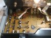
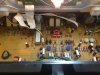
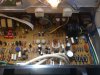
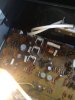
Thank you Kingbleu and kdris10. Don't have too much experience with SX-xx80 series and was not sure if those modules are original. The receiver works fine and it looks like someone just upgraded both filter caps from 8000uF/50V to 10000uF/50V. Everything else looks original to me. Going to do a full re-cap and probably replace some transistors.
Oleg LED
New Member
I have 2 sx-780s and they look original to me. I dont know of a way to know for sure. Looking at the solder joints might give you some clues.
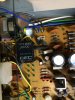
Thank you Kingbleu. I think the solder joints look normal. What do you think?


Kingbleu
Well-Known Member
Thank you Kingbleu. I think the solder joints look normal. What do you think?
View attachment 1834252 View attachment 1834254
The solder joints look like factory solder to me.
Oleg LED
New Member
Full recap? That's going to require some alignment afterward, and the x80 series is not a lot of fun to re-align, especially the tracking.
Sorry, I meant full re-cap for AF assembly GWK-118 (not a tuner assembly AWE-099). Did you mean it would require some alignment for tuner?
Oleg LED
New Member
That was my point. Changing some of the caps in the RF end invites an alignment.
I see. I have never tried to change e-caps in the RF board before. But I heard that if the tuner works fine it would be safe to change e-caps without any subsequent alignment. However, I am not sure if it is true or not?

When I started recapping I had an old pioneer 1010 that a guy gave me. It was a parts unit and in pieces. Once up and running, I used that one and replaced the electrolytic's in the tuner, keeping a detailed record of which ones and where they came from, in case something went wrong, I could make it whole again with the original caps. A lot of work with solder wick. Wouldn't do it again unless there's issues.
I do replace the coupling caps on other either side of the LP filters on the tuners that use them. It's the least one could do.
If "Watthour" say's it will cause trouble, he means it. He knows those smaller Pioneers inside and out.
I do replace the coupling caps on other either side of the LP filters on the tuners that use them. It's the least one could do.
If "Watthour" say's it will cause trouble, he means it. He knows those smaller Pioneers inside and out.
Last edited:

It should be safe to replace C27, C34, C40, C43, C44, C60, C61, C72 with indentical values (higher voltage is O.K.).
It's best to leave C37, C38, C41, C67, C76 original unless they have problems. It's also best if you can leave all the disc and film caps original.
It's best to leave C37, C38, C41, C67, C76 original unless they have problems. It's also best if you can leave all the disc and film caps original.
Oleg LED
New Member
Thanks a lot zebulon1 and Watthour for your comments and suggestions. I appreciate your help. The receiver is in good cosmetic condition and works fine. This is my first receiver from SX-xx80's and I want to keep it. I have some experience working on SX-450 and SX-750 but never on SX-xx80. I have already replaced 3 dial lamps and cleaned all pots with DeoxIT. Now working on e-cap list. Also want to replace all noisy/trouble transistors.
Zeb got you started. The two 2SA-726s on the RF board are notorious noise-makers.
The SX-780 in good condition is a decent performer with moderately efficient speakers (8Ω only, please). I think you'll notice a slight sound difference between that and the SX-750, possibly slightly more defined and flat, whereas the SX-750 tends to favor the lower frequencies a bit more in original form.
- Q25 in the power supply frequently runs quite hot, and can desolder itself. Investigate the circuit and foil traces for signs of excess heating.

Consider improving the heat sink for that component to eliminate overheating potential, being aware that those heat sinks are electrically live.

- Clean the RF board after replacing any components, including the under and around DIP packages, and allow them to dry thoroughly.

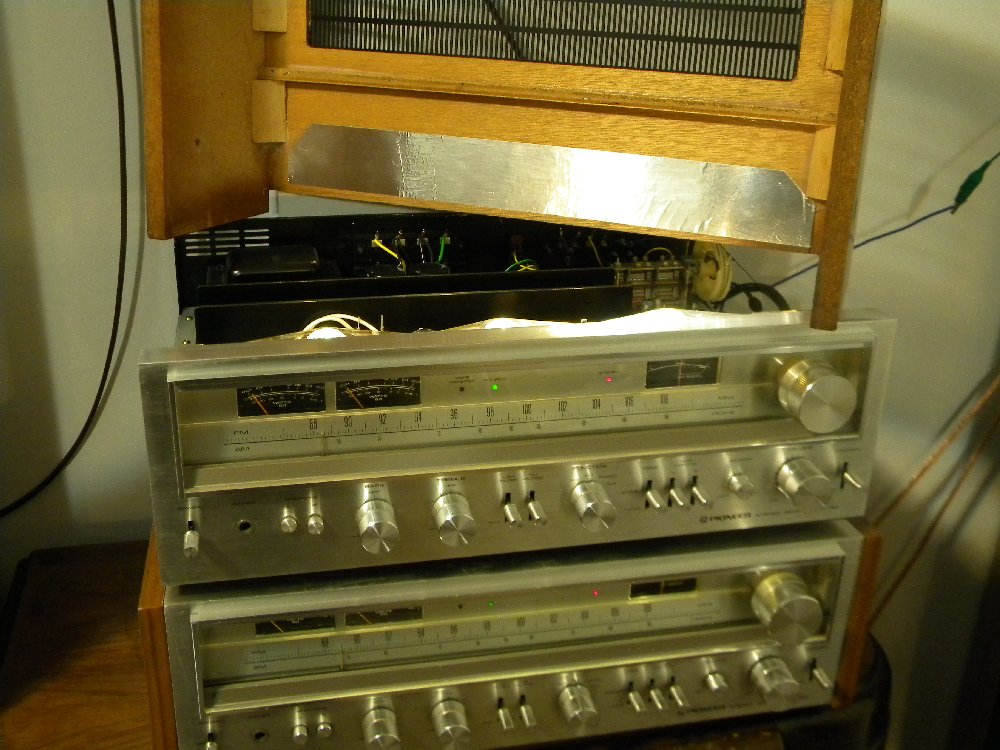
- Since you've replaced the dial lamps, you likely noticed the heating damage inside the top case directly over the lamps. Consider installing a strip of foil tape inside the top cover to reflect and diffuse the light and heat.
- Without desoldering the output darlington packs, refresh the thermal compound between them and the heat sink.

- Treat the cover to your favorite non-wood finish restorer/sealer, since the plastic veneer has already been exposed to 40 years of heat and sunlight.

- Check the fuses and holders. Of the half-dozen or so of these that I've been through, a high percentage had the fuses replaced at some point, apparently with whatever was available to make noise in lieu of the proper sizes.
- Check the main power transformer mounting screws. Several decades of thermal cycling can work them loose, potentially inducing noise. Similarly, check the chassis grounding lug screws.
The SX-780 in good condition is a decent performer with moderately efficient speakers (8Ω only, please). I think you'll notice a slight sound difference between that and the SX-750, possibly slightly more defined and flat, whereas the SX-750 tends to favor the lower frequencies a bit more in original form.
Oleg LED
New Member
Wow, it is a lot of meaningful and useful information. Thanks a lot Watthour!
I have some questions:
1. Is KSA992FBU transistor a good replacement for Q7 and Q8 transistors (2SA726) on tuner board AWE-099?
2. Would you recommend to replace any transistors on AF amplifier board GWK-118? I heard that 2SC1775 could be a troublemakers (Q5/Q6 and Q11/Q12 on AF board). Can I use KSC1845FTA transistor as a substitute for 2SC1775?
3. Do I need to remove a heat sink to refresh the thermal compound between STK-0050 and the heat sink? Or I just need to remove aluminum mounting plate?


4. Do you think it is a good idea to replace the relay?
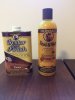
5. Would you recommend any particular restorer/sealer to treat the cover? I have Howard Restor&Finish and Howard Feed-N-Wax but not sure if it is suitable for plastic veneer?
I have some questions:
1. Is KSA992FBU transistor a good replacement for Q7 and Q8 transistors (2SA726) on tuner board AWE-099?
2. Would you recommend to replace any transistors on AF amplifier board GWK-118? I heard that 2SC1775 could be a troublemakers (Q5/Q6 and Q11/Q12 on AF board). Can I use KSC1845FTA transistor as a substitute for 2SC1775?
3. Do I need to remove a heat sink to refresh the thermal compound between STK-0050 and the heat sink? Or I just need to remove aluminum mounting plate?
4. Do you think it is a good idea to replace the relay?
5. Would you recommend any particular restorer/sealer to treat the cover? I have Howard Restor&Finish and Howard Feed-N-Wax but not sure if it is suitable for plastic veneer?
Oleg LED
New Member
Well, it is almost three weeks since my last post and the project was accomplished. Everything except two filter caps were original on both boards. The filter caps were upgraded from 8000uF/50V to Nichicon UKW series 10000uF/50V by previous owner. I am not sure if it is a best choice but decided to leave them for now. Below is a summary of what I did along with recap list I used in this SX-780. Any comments are very welcome.
1. GWK-118 board (AF Amplifier Assembly):
Changed all electrolytic caps on this board and 3 transistors: Q19, Q20 and Q25. I applied a new silicone thermal compound (Wakefield-Vette, 120 series) between each transistor and the heat sink but was not able to find a better heat sink for Q25 as Watthour recommended. Below is my recap list.
C103/C104 CEANL 2.2uF 50V UKL1H2R2KDDANA 2.2uF/50V
C105/C106 CEA 470uF 6.3V UPW1A471MPD 470uF/10V
C117/C118 CEANL 2.2uF 50V UKL1H2R2KDDANA 2.2uF/50V
C201/C202 CEA 4.7uF 35V UPW1H4R7MDD1TA 4.7uF/50V
C207/C208 CEANL 1uF 50V MKS2B041001C00JO00 1uF/50V
C213/C214 CEA 47uF 10V UPW1C470MDD1TD 47uF/16V (Schematic shows 47uF/6V, on the board 47uF/10V)
C217/C218 CEANL 4.7uF 25V UKL1H4R7KDDANA 4.7uF/50V
C227/C228 CEANL 0.22uF 50V QYX1H224KTP 0.22uF/50V
C229/C230 CEANL 2.2uF 50V UKL1H2R2KDDANA 2.2uF/50V
C301 thru C304 CEA 100uF 25V UPW1V101MPD 100uF/35V
C305/C306 CEA 47uF 35V UPW1V470MED 47uF/35V
C307/C308 CEA 100uF 50V UPW1H101MPD 100uF/50V
C309/C310 CEA 2.2uF 50V UPW1H2R2MDD1TD 2.2uF/50V
C311 CEA 220uF 16V UPW1E221MPD1TA 220uF/25V (Schematic shows 100uF/16V, on the board 220uF/16V)
C314 CEA 470uF 63V UPW1J471MHD3 470uF/63V
C315 CEA 220uF 63V UPW1J221MPD 220uF/63V
C316 CEA 47uF 50V UPW1H470MED 47uF/50V
C317 CEA 33uF 16V UPW1C330MDD6 33uF/16V
C318 CEA 10uF 16V UPW1C100MDD1TD 10uF/16V
C319 CEA 47uF 16V UPW1C470MDD1TD 47uF/16V
C324 thru C327 CEA 4.7uF 35V UPW1H4R7MDD1TA 4.7uF/50V (Only 2 caps on the board: C324 & C327)
C401 thru C404 CEA 0.47uF 50V MKS2B034701B00KO00 0.47uF/50V
C405 CEA 10uF 16V UPW1C100MDD1TD 10uF/16V
C406 CEA 220uF 6.3V UPW1A221MED 220uF/10V
No symbol CEA 4.7uF 35V UPW1H4R7MDD1TA 4.7uF/50V (This cap was not marked on the circuit board schematic. It is just to the right of C309 and the value was 4.7uF/35V)
Q11/Q12 NPN 2SC1775A-E or F KSC1845FTA NPN (didn't change this transistor)
Q13/Q14 NPN 2SC1885-R or S KSC2383YTA NPN (didn't change this transistor)
Q15/Q16 PNP 2SA912-R or S KSA1013YBU PNP (didn't change this transistor)
Q19 NPN 2SD325R-D or E MJE15032G NPN (changed to MJE's due to better power dissipation in comparison to original transistor)
Q20 PNP 2SB536-L or M MJE15033G PNP (changed to MJE's due to better power dissipation in comparison to original transistor)
Q25 NPN 2SD712-C or D MJE15032G NPN (changed to MJE's due to better power dissipation in comparison to original transistor)
2. AWE-099 (Tuner Assembly):
Changed only two notorious noise-makers transistors on this board: Q7/Q8, 2SA726 to KSA992FBU. The original transistors were gain matched (blue paint dots on the top of each). So, I matched two new transistors as well. I didn't change any caps yet. I think I will do it later keeping a detailed record of which ones and where they came from as zebulon1 and Watthour recommended in case if something went wrong. So far the tuner works great but the frequency is shifted by ~1MHz.
3. Carefully desoldered the output Darlington packs, removed the old thermal paste and applied a new silicone thermal compound (Wakefield-Vette, 120 series) between each pack and the heat sink.
4. Adjusted DC balance and power meters as recommended in the manual. The DC balance is ~5mV on each channel.
5. Replaced 3 dial lamps with incandescent bulbs. Installed a strip of foil tape inside the top cover to reflect and diffuse the light and heat as Watthour recommended.
6. Removed all knobs, face plate, and cleaned them with dish soap. Also, slightly polished all knobs by Mothers Mag & Aluminum polish. All pots have been cleaned and lubricated with DeoxIT.
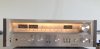
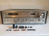
The receiver works great now, looks great and I really enjoy its sound. Thank you all for your comments and suggestions. Below are few pictures.
1. GWK-118 board (AF Amplifier Assembly):
Changed all electrolytic caps on this board and 3 transistors: Q19, Q20 and Q25. I applied a new silicone thermal compound (Wakefield-Vette, 120 series) between each transistor and the heat sink but was not able to find a better heat sink for Q25 as Watthour recommended. Below is my recap list.
C103/C104 CEANL 2.2uF 50V UKL1H2R2KDDANA 2.2uF/50V
C105/C106 CEA 470uF 6.3V UPW1A471MPD 470uF/10V
C117/C118 CEANL 2.2uF 50V UKL1H2R2KDDANA 2.2uF/50V
C201/C202 CEA 4.7uF 35V UPW1H4R7MDD1TA 4.7uF/50V
C207/C208 CEANL 1uF 50V MKS2B041001C00JO00 1uF/50V
C213/C214 CEA 47uF 10V UPW1C470MDD1TD 47uF/16V (Schematic shows 47uF/6V, on the board 47uF/10V)
C217/C218 CEANL 4.7uF 25V UKL1H4R7KDDANA 4.7uF/50V
C227/C228 CEANL 0.22uF 50V QYX1H224KTP 0.22uF/50V
C229/C230 CEANL 2.2uF 50V UKL1H2R2KDDANA 2.2uF/50V
C301 thru C304 CEA 100uF 25V UPW1V101MPD 100uF/35V
C305/C306 CEA 47uF 35V UPW1V470MED 47uF/35V
C307/C308 CEA 100uF 50V UPW1H101MPD 100uF/50V
C309/C310 CEA 2.2uF 50V UPW1H2R2MDD1TD 2.2uF/50V
C311 CEA 220uF 16V UPW1E221MPD1TA 220uF/25V (Schematic shows 100uF/16V, on the board 220uF/16V)
C314 CEA 470uF 63V UPW1J471MHD3 470uF/63V
C315 CEA 220uF 63V UPW1J221MPD 220uF/63V
C316 CEA 47uF 50V UPW1H470MED 47uF/50V
C317 CEA 33uF 16V UPW1C330MDD6 33uF/16V
C318 CEA 10uF 16V UPW1C100MDD1TD 10uF/16V
C319 CEA 47uF 16V UPW1C470MDD1TD 47uF/16V
C324 thru C327 CEA 4.7uF 35V UPW1H4R7MDD1TA 4.7uF/50V (Only 2 caps on the board: C324 & C327)
C401 thru C404 CEA 0.47uF 50V MKS2B034701B00KO00 0.47uF/50V
C405 CEA 10uF 16V UPW1C100MDD1TD 10uF/16V
C406 CEA 220uF 6.3V UPW1A221MED 220uF/10V
No symbol CEA 4.7uF 35V UPW1H4R7MDD1TA 4.7uF/50V (This cap was not marked on the circuit board schematic. It is just to the right of C309 and the value was 4.7uF/35V)
Q11/Q12 NPN 2SC1775A-E or F KSC1845FTA NPN (didn't change this transistor)
Q13/Q14 NPN 2SC1885-R or S KSC2383YTA NPN (didn't change this transistor)
Q15/Q16 PNP 2SA912-R or S KSA1013YBU PNP (didn't change this transistor)
Q19 NPN 2SD325R-D or E MJE15032G NPN (changed to MJE's due to better power dissipation in comparison to original transistor)
Q20 PNP 2SB536-L or M MJE15033G PNP (changed to MJE's due to better power dissipation in comparison to original transistor)
Q25 NPN 2SD712-C or D MJE15032G NPN (changed to MJE's due to better power dissipation in comparison to original transistor)
2. AWE-099 (Tuner Assembly):
Changed only two notorious noise-makers transistors on this board: Q7/Q8, 2SA726 to KSA992FBU. The original transistors were gain matched (blue paint dots on the top of each). So, I matched two new transistors as well. I didn't change any caps yet. I think I will do it later keeping a detailed record of which ones and where they came from as zebulon1 and Watthour recommended in case if something went wrong. So far the tuner works great but the frequency is shifted by ~1MHz.
3. Carefully desoldered the output Darlington packs, removed the old thermal paste and applied a new silicone thermal compound (Wakefield-Vette, 120 series) between each pack and the heat sink.
4. Adjusted DC balance and power meters as recommended in the manual. The DC balance is ~5mV on each channel.
5. Replaced 3 dial lamps with incandescent bulbs. Installed a strip of foil tape inside the top cover to reflect and diffuse the light and heat as Watthour recommended.
6. Removed all knobs, face plate, and cleaned them with dish soap. Also, slightly polished all knobs by Mothers Mag & Aluminum polish. All pots have been cleaned and lubricated with DeoxIT.
The receiver works great now, looks great and I really enjoy its sound. Thank you all for your comments and suggestions. Below are few pictures.
Attachments

Oldsansui441
Super Member
Nice work Oleg, looks great.


