

You are using an out of date browser. It may not display this or other websites correctly.
You should upgrade or use an alternative browser.
You should upgrade or use an alternative browser.
SX-1010 won't Power On...
- Thread starter D.E.K
- Start date


D.E.K
Loader
I'm looking, looks like Q8's base connection, the two pads further over are a less used part of the circuit. I will edit this post after I look at the other area. edit: The less used area isn't- there's an anti-oscillation capacitor there that is needed.
Both areas should be repaired after a thorough cleaning of the entire board, there are two ways (well, more but..) to fix the interrupted traces, both involve connecting the solder pads back together, one with insulated wire from pad to pad when there is no chance of the loose copper shifting and shorting out something, and the other uses bare wire, with the green coating scraped off the traces, and the bare wire is soldered along the trace's bare copper to provide mechanical support as well as electrical conductivity.
I'll look for a junk board I can demonstrate on, but I don't have much junk around. Maybe somebody else can contribute on the subject?
I believe what ZeroJunk used in Post #288, Page 20 is the 2nd method you described, the bare copper wire method. From C4's (-) Joint to C3's (-) Joint

Yes, I see it, took a while to find it all to get the references.
I didn't want this request to be lost ( a lot of posts in between), but since the board has been moved, we can do the transistors and capacitors.
The readings are for a baseline, to see if there is a problem, and if there has been any improvement.
I'm logging off for tonight.
<snip>
(on the protection board)
You can connect the voltmeter between pin 1 (and pin 3) and ground, and watch the amplifier's output voltage, it's probably jumping around on at least one of the channels due to all that salt condensed on the bottoms of the transistors.
Did we ever measure the power supply voltages? You may want to do that first, You need to watch these voltages and as the receiver goes in and out of protection to see if they are doing it, the old garbage in - garbage out principle. The amplifiers can't be expected to be stable when the power supply is jumping all over the place.
The AWR054 power supply board:
pin 14 +56v
pin 13 +35v
pin 10 -56v
pin 8 13.4v
Basically, we're talking about a 100% cleaning job,starting with the power supply and amplifiers, with the other circuits later to quiet them down. We can consider the protection circuit trustworthy now.
I didn't want this request to be lost ( a lot of posts in between), but since the board has been moved, we can do the transistors and capacitors.
The readings are for a baseline, to see if there is a problem, and if there has been any improvement.
I'm logging off for tonight.

Remember that "chirping" noise while looking for stations? It is still there, alive and loud
There has been a thread or post on the "chirping" somewhere on this forum. I can't remember what the cause was. But, mine does it also.

D.E.K
Loader
See post #117, page 8, this thread.
Yes, according to cademan, it's normal but I'd like to draw your attention to #119 on the same page. "It is a glitch" says Mark.
D.E.K
Loader
Okay Mark, I am not sure how to take those readings. On the Protection Board, you want me to test Pin 1 and Pin 3. To test that, the Red Lead of the multimeter goes on the pins and the Black Lead goes on ground. Unfortunately since this is the first ever time I am looking at a schematic, I cannot find ground on it (Schematic Shot Attached). These readings are taken while the unit is Powered ON right? Do you want me to take double readings, one while the relay is ON and one while it's OFF? How about the scale on the voltmeter, I guess I should keep it at 200V?
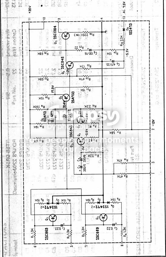
Now the Power Supply Board (AWR-054-A)... Now the attached Shcematic Shot shows ground being somewhere between Pin 2 and Pin 3 but for the life of me I cannot find it, probably I don't know how to look at it.
Edit: Is it by any chance Pin 7?
Other than that, same questions for this one as well. Readings taken while the unit is ON, and two sets of readings while relay is engaged and while it is disengaged?
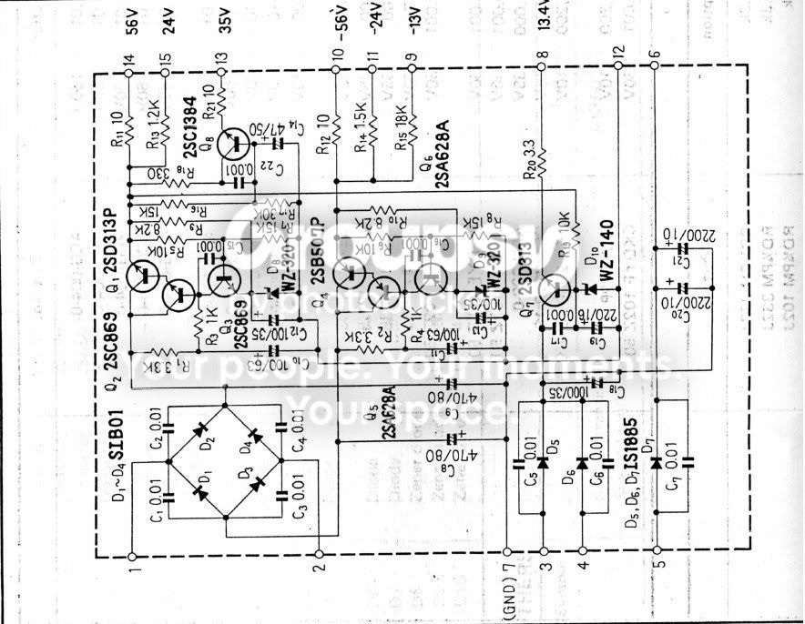
Now the Power Supply Board (AWR-054-A)... Now the attached Shcematic Shot shows ground being somewhere between Pin 2 and Pin 3 but for the life of me I cannot find it, probably I don't know how to look at it.
Edit: Is it by any chance Pin 7?
Other than that, same questions for this one as well. Readings taken while the unit is ON, and two sets of readings while relay is engaged and while it is disengaged?

D.E.K
Loader
You gotta sick pin 10. Too low. Pin 13 is slightly low with relay on but not much.
The rest look good.
A sick Pin 10 eh? Well then, we're just going to have to heal it aren't we.
But where is GROUND on the Power Protection Circuit?
 :thmbsp: You're learning quickly.


D.E.K
Loader
Sure, I'm game. Whatever needs to be done.
Here are the readings for the Power Protection Board. These are taken when the Relay was OFF:
Pin1:
At 20V Scale, it is 0.03
At 2V Scale, it jumps all over the place Lowest 0.019 - Highest 0.039
Pin3:
At 20V Scale, it is 0.02
At 2V Scale, it jumps all over the place Lowest 0.019 - Highest 0.026
I will take some readings later on with the Relay ON. It gets harder and harder for the relay to click on as the receiver heats up. And still, the heat sink that is on the Power Supply Board is SCORCHING.
You guys have been doing GREAT
(I've been busy too... look down.....)
Re: chirping: "share that glitch" I didn't express myself well, it is a characteristic of a lot of TOP END Pioneers that use a reed relay to mute the fm between stations. it also shows up on some models even when the FM isn't selected because some tuner circuits are still live.
EchoWars and myself have both encountered it, and haven't found the time to figure out either a targeted repair(my theory is age related defect) or a fix. It has something to do with the FM I.F. Chip staying live and generating a dirty (chattering) muting signal. chirp - chatter - whatever.
Bottom line: we gotta live with it, it's not a serious problem and someday it may be explained or conquered.
NOW to Pin 10 (-56v)and by inference pins 9 (-13v) and 11 (-24v) as well.
That's the AWR054 board.
Zerojunk and i have tangled with that board before:
http://www.audiokarma.org/forums/showthread.php?p=2331911&highlight=AWR054#post2331911
Even though the pin 1 and pin 3 VOLTAGES LOOK GOOD , the protection is not kicking in because Pin 2 of the protection board needs -13v to balance out the circuits, the loss of pin 10's -56 volts also means the loss of pin 2's -13v.Usually the -13v is made quite differently in Pioneer receivers, but on the 1010, this is what we're stuck with.
So we gotta fix the -56v supply on the power supply board.
Q4 2sb507 to-220 bce
b507
one 512-KSA940TU_Q pnp to-220 bce 150v 1.5a 25w 4mhz 40-140hfe $0.54
Q5 Q6 2sa628 to-92 BCE 25v .1a .15w 100mhz 800hfe
a628 (BCE)
two 512-KSA1013YBU to-92 ecb 160v 1a .9w 50mhz 160-320hfe $0.17 ea
D9: wz-320
512-1N5257B Fairchild 33 V, 0.5W zener $0.05 ea
C11 100uf (63v) 100v 647-UPW2A101MHD $0.87 ea
C13 100uf (35v) 63v 647-UPW1J101MPD1TD $0.37 ea
the above parts are just for the -56v regulator, to do the entire board, the parts list in zerojunk's thread can be used, and I'll get the Q designations edited into it for the entire power supply so you can navigate it a bit more easily.
See, that's why I wanted to read the power supply voltages, think how discouraging it would be to rebuild BOTH amps and STILL have the thing in protection. I will look at the list of parts you have to see if you have reasonable substitutes in hand with the PA parts.
This post is still being edited until this line disappears....
(I've been busy too... look down.....)
'
You recapped C1 & C2 as well as replaced Q3 on the awm-039 muting ckt assy?
And it still chirps?
If so, this is crazy just how many models share that glitch.
NOW I gotta get my hands on a 1010 too. sigh....
Re: chirping: "share that glitch" I didn't express myself well, it is a characteristic of a lot of TOP END Pioneers that use a reed relay to mute the fm between stations. it also shows up on some models even when the FM isn't selected because some tuner circuits are still live.
EchoWars and myself have both encountered it, and haven't found the time to figure out either a targeted repair(my theory is age related defect) or a fix. It has something to do with the FM I.F. Chip staying live and generating a dirty (chattering) muting signal. chirp - chatter - whatever.
Bottom line: we gotta live with it, it's not a serious problem and someday it may be explained or conquered.
NOW to Pin 10 (-56v)and by inference pins 9 (-13v) and 11 (-24v) as well.
That's the AWR054 board.
Zerojunk and i have tangled with that board before:
http://www.audiokarma.org/forums/showthread.php?p=2331911&highlight=AWR054#post2331911
Even though the pin 1 and pin 3 VOLTAGES LOOK GOOD , the protection is not kicking in because Pin 2 of the protection board needs -13v to balance out the circuits, the loss of pin 10's -56 volts also means the loss of pin 2's -13v.Usually the -13v is made quite differently in Pioneer receivers, but on the 1010, this is what we're stuck with.
So we gotta fix the -56v supply on the power supply board.
Q4 2sb507 to-220 bce
b507
one 512-KSA940TU_Q pnp to-220 bce 150v 1.5a 25w 4mhz 40-140hfe $0.54
Q5 Q6 2sa628 to-92 BCE 25v .1a .15w 100mhz 800hfe
a628 (BCE)
two 512-KSA1013YBU to-92 ecb 160v 1a .9w 50mhz 160-320hfe $0.17 ea
D9: wz-320
512-1N5257B Fairchild 33 V, 0.5W zener $0.05 ea
C11 100uf (63v) 100v 647-UPW2A101MHD $0.87 ea
C13 100uf (35v) 63v 647-UPW1J101MPD1TD $0.37 ea
the above parts are just for the -56v regulator, to do the entire board, the parts list in zerojunk's thread can be used, and I'll get the Q designations edited into it for the entire power supply so you can navigate it a bit more easily.
See, that's why I wanted to read the power supply voltages, think how discouraging it would be to rebuild BOTH amps and STILL have the thing in protection. I will look at the list of parts you have to see if you have reasonable substitutes in hand with the PA parts.
This post is still being edited until this line disappears....