

You are using an out of date browser. It may not display this or other websites correctly.
You should upgrade or use an alternative browser.
You should upgrade or use an alternative browser.
SX-1010 won't Power On...
- Thread starter D.E.K
- Start date

Here's the transistor testing thread:
http://www.audiokarma.org/forums/showthread.php?t=43186
post #11 has an explicit test protocol and typical results for both polarities of transistor.
This is the link I gave him when he PM'd me, he has stated after he read EW's transistor test protocol he has no knowledge of emitter, diode, etc. So I sent pics with my meter to picture how to test.
Be REAL careful with that little horseshoe shaped diode on the heatsinks, the wire LOVES to break, and it is the hardest to find part in the unit. Replacing just about everything else is easier.
He already removed the heatsink before I could even say it.
 I hope he's careful with that.
I am really anxious to get it going but aht this point with 2 bad transistors, that's not going to happen. Speaking of transistors, I measured following EW's instructions and yes, 2 of them are gone, the rest seem to be fine. Range between 0.63 and 0.65
Just don't power up that sucker unless you want to turn it into a BOAT ANCHOR!!

D.E.K
Loader
No, no power. I even removed the main fuse just in case. No broken wires on the horseshoes either, assuming that you're talking about the horseshoes in the attached pictures? No worries, I might be lacking knowledge, but I am gentle enough. Also, I tested those 2 diodes and like you said, I get the reading one way and one way only. One of them 0.675 and the other is 0.685
Does that sound right?
Does that sound right?
No, no power. I even removed the main fuse just in case. No broken wires on the horseshoes either. No worries, I might be lacking knowledge, but I am gentle enough. Also, I tested those 2 diodes and like you said, I get the reading one way and one way only. One of them 0.675 and the other is 0.685
Does that sound right?
Yes, it sounds about right. I just now tried mine with the diode I already pulled from my SX-1010, it still couldn't read. I got CHEAP meter though. Works for now until I get the fancy one.
D.E.K
Loader
Yes, it sounds about right. I just now tried mine with the diode I already pulled from my SX-1010, it still couldn't read. I got CHEAP meter though. Works for now until I get the fancy one.
Cheap meter? :lmao: I paid $30 for mine, talk about cheap!
D.E.K
Loader
Wait, I recalled there's a diode next to the STV-3 diode (rectangular box). Which diode did you test? The cylinder one or the rectangle box?
hang on a sec...
Cheap meter? :lmao: I paid $30 for mine, talk about cheap!
I beat that by $15.
Now talk about cheap.:huge:
DANGER WILL ROBINSON DANGER!!!!!!!!! 
Don't use the 9v battery straight on ANY diode, you must use a current limiting resistor, you only want a maximum of 7 milliamps through the diode.
Use at least 1200 ohms of resistance in series with the battery and diode. Then measure across the diode.
Too much current will destroy the diode. Without the resistor you can get too much current.
Don't use the 9v battery straight on ANY diode, you must use a current limiting resistor, you only want a maximum of 7 milliamps through the diode.
Use at least 1200 ohms of resistance in series with the battery and diode. Then measure across the diode.
Too much current will destroy the diode. Without the resistor you can get too much current.
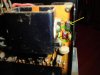
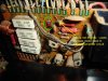
These are the ones you need to test (see pic). One pic shows what looks like a bias diode used in different amplifier circuit. I'd just replace those diodes in both pic since one drops probably less voltage than the other. But they must be removed from the circuit in order to do the test.
Attachments
DANGER WILL ROBINSON DANGER!!!!!!!!!
Don't use the 9v battery straight on ANY diode, you must use a current limiting resistor, you only want a maximum of 7 milliamps through the diode.
Use at least 1200 ohms of resistance in series with the battery and diode. Then measure across the diode.
Too much current will destroy the diode. Without the resistor you can get too much current.
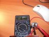
I meant to put the diode in series with the voltmeter when connecting to the 9v battery. At least it works for me. I agree don't want to put both terminals of the battery straight on the diode.
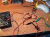
I would then flip the diode to see if it will conduct another direction. (See pic 1) My meter may show lower voltage, my 9v battery is weak and was used in this meter so it only contains 7.2v and dropped to 6.3. FYI - your readings may show different with stronger 9v battery.Edit: 2nd pic shows what Markthefixer have stated. Here it is more reliable testing. Go along with the 2nd pic. You will notice 3 different alligator clip lead colors for easy ID along with 2.2k resistor I used with this test and see here is 1.6v drop measured on the meter. Also notice the black lead is connected to the side with green dot and the - side of the battery(big button). The diode MUST be removed to do this test.
Attachments
At least they're not shorted. But we still have to know if they're not open too. If that was my receiver, I personally would just replace them. Even with both of my diodes were original and good, I replaced both of my originals with two in series of Fairchild UF4004 diodes(mouser part #512-UF4004_Q) each. But if you want 2nd opinion, Markthefixer will have a good answer.:thmbsp:
Attachments

I certainly would replace them, one problem though. I don't know how! So at this point I'll have to assume they are okay.
:lmao:
You will know how when you get to that point. Let me ask you, have you EVER solder before? I mean electronic soldering? Not pipe or anything else soldering. Speaker wire soldering? Do you have soldering iron?
I mentioned earlier about replacing all 4 emitter resistors on the bad channel. I am still wondering about the ohm measurment of the other 4 emitter resistors on the "good" channel?
I'm gonna call it a night for now. I know how anxious you are having this thing going. It's an excellent receiver. Be patient, you'll get there.
Also, if it means anything, there is no continuity between the two points I circled in the attached picture. It looks like one end is soldered to the large plate inside. Some kind of grounding??
It is the resistor. Not much of a concern. It has nothing to do with your problem.
The resisor's color code is red red blue, and it connects one side of the power line to the chassis ground as a safety measure. The resistor limits leakage current to a human safe level, and ties the chassis to neutral. That's why the plugs are not polarized, to compensate for mis-wired receptacles - they can be inserted in the opposite direction to get the neutral correct.
red red blue is 22 million ohms, which gives 5.4 microamps at 120v.