• The move to the new server is done. There are some software and database maintenance updates in process. This has us passing the hat around to help out. We appreciate any donations. Seriously, even a dollar helps. The payment page may be found here - https://www.audiokarma.org/support.html

SX-1050 Blowing Fuses

That stinks that it isnt going well,maybe you should take a break from and see if you feel like getting back to it in a couple of days.
Im sure that mark will chime in,maybe some close up pictures of the board and the transistor placement etc to see if there is something visual that mark might see.
Have all of the loads been disconnected from the board and is it still getting hot with the loads disconnected.
DONT DO ANYTHING that Mark has not told you to do.(meaning dont listen to me)Im just curious as to where you are at.
Good Luck.
Steve
 
Which of these wires are still disconnected?

5 & 6 +13v power
8 -60v power
(the draws on 9, 10 & 11 are low enough even if shorted (R17 = 820) not to smoke R19)
(same for 13, 14 & 15 (due to R9 = 520) and R1)
16 & 17 +60v power

Be sure they all are off.

You could:
Replace r20 with a 470 ohm resistor (23v / 470 ohms = 50ma) and try applying power directly, the variacing process may be contributing IF 5 & 6 ARE disconnected. 23 * 23 / 470 = 1.125 watts so 5 x 100 ohm 1/4 w resistors would do it.

With no load the 470 will allow the regulator to either function, or we can take voltage measurements.

OR

BE SURE 5 & 6 are disconnected then you could ramp up the variac slightly, until the resistor gets warm and look for where the short is by taking voltage readings

OR

BE SURE 5 & 6 are disconnected then you could replace r20 with a wire, and slowly ramp up the variac looking for what else heats up, but the transistors could be destroyed.

OR

You could remove Q9, Q10 & Q11, connect Q9's c to e with a wire, and ramp up the variac looking for what heats up, protecting the transistors.

If 5 & 6 are disconnected, the caps are correctly inserted, and the transistors are correctly inserted, this makes no sense.

Perhaps you had better take some pictures.
 
5 & 6
8
16 & 17
all disconnected

smoking at 50 watts
i'll take pics and post in the morning my camera is home i'm at work
 
mark , should i replace R20 with a 470 ohm 1/2 watt or 1/4 watt resistor? and when powering up don't use the variac?

also just to let you know the board was smoking earlier with all wires attached
 
I skimmed the thread, but did you disconnect the wires from Pin 5 and 6? If it's still trying to smoke the 10 ohm resistor with these wires removed, then you got a cap in backwards or a transistor installed incorrectly.
 
echo, yes i disconnected 5&6, i rechecked the caps and the transistors that i replaced, and all of them look to be in correctly...i will take pics and post them later
i am far from being a pro, maybe you guys might see something that i am not, and hopefully it's as easy as turning a cap around or resetting the leg of a transistor..

thanks
 
You could:
Replace r20 with a 470 ohm resistor (23v / 470 ohms = 50ma) and try applying power directly, the variacing process may be contributing IF 5 & 6 ARE disconnected. 23 * 23 / 470 = 1.125 watts so 5 x 100 ohm 1/4 w resistors would do it.


Perhaps you had better take some pictures.

5 x 100 ohm 1/4 watt = 500 ohms 1.250 watts

Maybe you should just pull C24 (again??) with 5 & 6 disconnected there should be very little capable of allowing that much current through.

Just to clarify, the capacitors have their NEGATIVE terminal marked, the Nichicon 647-upw's have a brown body with a WHITE stripe which is the NEGATIVE terminal. I JUST visually re-verified this.

The problem is if the transistors or capacitors are backwards, there is no telling all the damage that has been done to the new components, they must be retested individually out of circuit. I seem to remember something about Q6 & Q7 being in wrong..

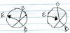
as for the transistors:
Ignore the numbers, pay attention to the orientation in the view....

attachment.php


attachment.php


attachment.php


Ignore the numbers, pay attention to the orientation in the view....
 
Just to clarify, the capacitors have their NEGATIVE terminal marked, the Nichicon 647

mark, i know how to install the caps, it's the transistors that i have a problem with, but to be honest i think i have it right this time...i checked and rechecked everything i replaced, which included all the caps and all the transistors, along with all the diodes...everything looks right to me, but like i said i'm not a pro
i'm posting a drawing with my interpretation on how the silkscreened transistor legs attach to the board, i have followed this along with the data sheets for each and every transistor i have replaced, if you need camera shots of the actual transistor placements let me know, it might be difficult to see them though.....let me know if i am wrong with this
 

Attachments

  • img079.jpg
    img079.jpg
    13.7 KB · Views: 18
Your ecb placements are correct.

Remove the three transistors: Q9, Q10 & Q11

Test the transistors while they are out of circuit.

DISCONNECT PINS 18 & 19 , Their voltage depends upon the 13v circuit to set the correct level and things could be hurt if it goes too high.

leave R20 in, and power it up and see if it smokes. We are looking for shorts between R20 and Q9.

Next if no smoke, (otherwise stop) C24 is removed and the C and E connections of Q9 will get a jumper wire connecting them. If no smoke measure the voltage across D4. It should be about 6 volts.
 
mark, i should remove Q9-Q10-Q11....then disconnect pins 18 & 19, do i still disconnect 5&6, 8 & 16-19, or should i connect those...am i using the variac to power up
 
mark, i should remove Q9-Q10-Q11....then disconnect pins 18 & 19, do i still disconnect 5&6, 8 & 16-19, or should i connect those...am i using the variac to power up

yes

q9, q10 , q11 all removed

pins
5, 6,(+13)
8, (-60)
16, 17 (+60)
18, 19 (+5.4v)
all disconnected
 
mark, did as instructed, brought it up on the variac up to 70 watts...then C15 blew up, exploded from the top....was checking for smoke and then pssssst white smoke in the face at 5:00am...what a wake up call!! looks like i have some problems

R20 didn't smoke this time
 
mark, did as instructed, brought it up on the variac up to 70 watts...then C15 blew up, exploded from the top....was checking for smoke and then pssssst white smoke in the face at 5:00am...what a wake up call!! looks like i have some problems
Well I could be wrong but maybe thats a good thing at this point as long as nothing else was hurt (other than the warm wet spot you are now sitting in).
That would have scared the crap out of me.
Couldnt you have waited until tommorow to light the fire works??
Sorry I couldnt resist
 
Is C15 original or did you replace it?

To me at least the difference between R19, R20 and R1 is quite clear.

R19 is the closest to the off board connections
R20 is pretty close to the middle of the board
R1 is the furthest of the three to the opposite side of the board.

There is a LOT that is not adding up.

There aren't many connections left on the board holding it in.

I'm starting to wonder if might be a good idea to send it to me.

What about those pictures?
 
thanks steve....is your last name martin...steve martin? lol
it was sort of a fizzled out bottle rocket...scared the crap out of me

thanks for the joke, at this time of the day i need something positive before i go to bed
 
well I Could Be Wrong But Maybe Thats A Good Thing At This Point As Long As Nothing Else Was Hurt (other Than The Warm Wet Spot You Are Now Sitting In).
That Would Have Scared The Crap Out Of Me.
Couldnt You Have Waited Until Tommorow To Light The Fire Works??
Sorry I Couldnt Resist

it Is Tomorrow...
 
c15 was replaced, mark maybe i'll just package it with the sx-1250 i was supposed to send you last month, i haven't gotten around to that yet, my company (honeywell) is closing operations here and moving to new mexico...i've been busy with deciding what i'm going to do with all my free time soon

i will post pics later today if that helps...happy 4th
 
c15 was replaced, mark maybe i'll just package it with the sx-1250 i was supposed to send you last month, i haven't gotten around to that yet, my company (honeywell) is closing operations here and moving to new mexico...i've been busy with deciding what i'm going to do with all my free time soon

i will post pics later today if that helps...happy 4th

Just the power supply board, both in the same box would destroy the board.

Keep it light, I'll keep it reasonable, and try to get it back quick. Power supplies aren't hard, and I have all the transistors (but NOT the caps) in house.
 
mark, i'm back after many months, and now unemployed thanks to freaking honeywell,after working for them for 29 years they decide to close and move to new mexico 1 year short of my 30 year pension... anyway, this thing we were working on,the power supply board, i got lucky and found one on epay for 9.99 along with a few toggle caps....i just installed it into the 1050, dim bulb tester, passed that test, now to full current and voila!the damn thing sounds like new, just a little scratchy in the volume, but i will de-oxit that and all the other pots and switches...this thing has been sitting in my garage for the last 6 months and one of my cats has adopted it as his bed, i had the cover off and he would sleep in between the tuner board and the transformer and big caps.....just wanted to let you and everyone here know , you are the man!! and thanks again
do you still have any time for the 1250? no power, blows fuses and cooks the microtemp?thats in the garage too, but it's a real beauty and it's way beyond my little knowledge....let me know...thanks

tim
 
Time as in remote, or hands on at the bench? That's unclear.

Sounds like a short in the outputs that's preventing the soft start from actuating and blowing the main fuse. Check all the fuses on the pc board, the 12 amp fuse for the unit isn't on it. Fu1(pin 3, orange wire) and Fu2(pin 4, orange wire) should be carefully checked, as this will also inhibit the soft start.

Then check all 8 outputs, ohming from the collector to the emitter looking for shorts, OR just plain pull all 8. There is a DC feedback path, that once the outputs are removed and their SOCKETS INSULATED, we can power up the unit (ON a dim bulb tester) and take voltage readings to see if the problems go deeper in the amp. It has base resistors (4.7 ohm 1 watt) that may have prevented cascade failure going back into the drivers etc...

But that's a far less expensive fix than replacing the outputs....
 
Back
Top Bottom