You are using an out of date browser. It may not display this or other websites correctly.
You should upgrade or use an alternative browser.
You should upgrade or use an alternative browser.
Register to hide this ad
Thorsten R.
Super Member
Was the device in use in the meantime or did it sit for those years because you did not like it? In that case I would get rid of the old electrolythics because it may well be they are dried out and they have to be reformatted anyway after that time on the shelf. And then: Check bias and (when possible) symmetry of the poweramp. When I power up an old amp after work I protect the power amp transistors with 100 Ohms resistors between the collectors and + resp. - Vcc. Then they are protected and you can make a check whether the circuit is working.

Wyatt Weeks
Member
dustmaker - what do you mean by 'organized manner instead of just replacing parts'? Are you saying you only want to replace components that are currently acting up? or all potentially troublesome components?

dustmaker
Active Member
No- I meant simply to follow your guidance as to which board(s) to address first. If I were to do it on my own, I would start at power supply and replace all electrolytic, diodes, transistors. Once done, I move on to another board. But I really don’t know if that is the best approachdustmaker - what do you mean by 'organized manner instead of just replacing parts'? Are you saying you only want to replace components that are currently acting up? or all potentially troublesome components?
dustmaker
Active Member
The receiver has been on a shelf (storage) for 17 years. When I first got it, I tried it out but the sound wasn’t as good as other receivers, so I didn’t use itWas the device in use in the meantime or did it sit for those years because you did not like it? In that case I would get rid of the old electrolythics because it may well be they are dried out and they have to be reformatted anyway after that time on the shelf. And then: Check bias and (when possible) symmetry of the poweramp. When I power up an old amp after work I protect the power amp transistors with 100 Ohms resistors between the collectors and + resp. - Vcc. Then they are protected and you can make a check whether the circuit is working.

merlynski
Curmudgeon Electronicist
First take a whole bunch of pictures before you do any more than remove the bottom plate and the top cover, at many angles, including close ups of wire routing and wire clips holding wires. Proper wire routing is VERY important to getting a clean low noise floor, the engineers spend lots of time getting the routing correct. You will want to put it back in the clips and ties just the way it was.No- I meant simply to follow your guidance as to which board(s) to address first. If I were to do it on my own, I would start at power supply and replace all electrolytic, diodes, transistors. Once done, I move on to another board. But I really don’t know if that is the best approach
Power up on DBT and let it sit for a while. If it is gonna blow something early, better on the DBT. If it is happy on DBT for at least 15 minutes (an hour if you can stand the wait) go on full mains. Then I would start with measuring and documenting power supply voltages on C1, C2 (main caps) and the AWR-104 and AWR-103 to see if there are any issues to start with and have a known reference starting point.
Yes I am being ODC and a perfectionist . . .

Last edited:
Wyatt Weeks
Member

merlynski
Curmudgeon Electronicist
The first thing I would do is figure out what is causing it to sound "scratchy" (pots, switches, or a component failure) and fix that, before you start randomly replacing anything.
IF the problem is scratchy controls and Deoxit is the fix, the disassembly needed to get to the controls is significant, and is the same procedure needed to access the PCBs to replace components during refurbishment. If the scratchiness is aging silicon it will be subsumed in the refurb process. If the 'scratchy' control or circuit can be identified before disassembly is started, so much the better, then fix it along the way. The front panel controls are densely packed on multiple PCBs, buried under each other, with lots of hardware to be removed and kept track of in the process..
The OP is on the right track,:IMHO:
YMMVI want to do this in an organized manner i
Last edited:
dustmaker
Active Member
I saw it and used it to order a few more parts. I should have 95+% of parts I’ll need, except I haven’t ordered main caps, relays or power transistors.. as I get to the power amp, I’ll decide on the transistors. The other components I’ll make a decision as I go forwardIn case you haven't seen it yet here, I'm finalizing a SX-1050 list to refurb my own unit. Hopefully that helps with component selection.
merlynski
Curmudgeon Electronicist
Main caps can be easily replaced at any time, they are in the open. The protection circuit is easy to access, and the protection relay is easy to change while the protection board is dismounted. The power supply AWR-104 is kind of buried. I changed the electrolytic caps on mine. I did not find any bad rectifiers, and did not change any of them. The AWR-103 power supply board required a lot of wires being released from their clips and ties to allow the board to slide out enough to work on it, but I did not need to unwrap or unsolder any to do so. I replaced all the transistors, and the electrolytic caps. I found several of the e-caps to be open. The Zener diode voltages (and related regulator voltages) were all in spec and were not changed. Several of the transistor replacements were TO-126 packages instead of TO-92. I added heatsinks to some that did not have them, and better heatsinks to some that did. I increased R21 from 2W to 5W and mounted it much higher, away from the board and the other components. The little white nylon mounting posts are quite brittle with age and heat. I used threaded nylon standoffs, screws and nuts to replace the one I broke. 
Wyatt Weeks
Member
merlynski - do you recall the part numbers for the new heat sinks you added/replaced on awr-104?
dustmaker
Active Member
OK - I guess we begin
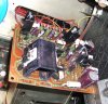
I already started on the AWR-104A board. One of the 470mF caps was swollen, so I replaced both. I did not replace the 2200mF since I don’t have one and I already placed my Mouser order. That one will be down the road.
The -1050 does power up fine while not on DBT. I’ll start measuring and recording my voltages before I go further.
I already started on the AWR-104A board. One of the 470mF caps was swollen, so I replaced both. I did not replace the 2200mF since I don’t have one and I already placed my Mouser order. That one will be down the road.
The -1050 does power up fine while not on DBT. I’ll start measuring and recording my voltages before I go further.

Was it the one nearer to the bridge rectifier? I just did a 1050 and it had one swollen cap too.OK - I guess we begin
I already started on the AWR-104A board. One of the 470mF caps was swollen, so I replaced both.
dustmaker
Active Member
Yes, the one closest to the rectifier.Was it the one nearer to the bridge rectifier? I just did a 1050 and it had one swollen cap too.
Last edited:
dustmaker
Active Member
I didn’t measure as mine were original but I replaced with 100v 105degree caps. Should hold up betterMaybe the heat from the rectifier cooks them. Either way, both of the 470 uf 80v caps in mine tested right around 220 uf, and were replaced.
dustmaker
Active Member
Merlynski
I printed off my service manual and recorded all pin voltages for both -103 and -104. Initial readings are within reason of schematic voltages except numbers in red. Below are voltage for the power supply circuits:
AWR-104
P 3: +62.0 vdc
P 5: -62.0 vdc
P 6: +76.9 vdc
P 7: -79.0 vdc
P 8: +23.4 vdc
P 1: 7.8 vAC
P 2: 46.6 vAC
P 4: 46.6 vAC
P 9: 0
P10: 18.69 vAC
P11: 18.77 vAC
P12: 18.78 vAC
P13: 58.9 vAC
P14: 58.9 vAC
P15: 7.92 vAC
AWR-103
P 1: +23.38 Vdc
P 2: +76.8 vdc
P 3: -78.8 vdc
P 4 & P12: 0 vdc
P 5 & P6: +13.69 vdc
P 7: -13.33 vdc
P 8: -61.4 vdc
P 9: 555 mvdc
P10 & P11: 568 mvdc
P13 &P14: +26.63 vdc
P15: +32.75 vdc
P16 P17: +63.6 vdc
P18 P19: +5.47 vdc
I printed off my service manual and recorded all pin voltages for both -103 and -104. Initial readings are within reason of schematic voltages except numbers in red. Below are voltage for the power supply circuits:
AWR-104
P 3: +62.0 vdc
P 5: -62.0 vdc
P 6: +76.9 vdc
P 7: -79.0 vdc
P 8: +23.4 vdc
P 1: 7.8 vAC
P 2: 46.6 vAC
P 4: 46.6 vAC
P 9: 0
P10: 18.69 vAC
P11: 18.77 vAC
P12: 18.78 vAC
P13: 58.9 vAC
P14: 58.9 vAC
P15: 7.92 vAC
AWR-103
P 1: +23.38 Vdc
P 2: +76.8 vdc
P 3: -78.8 vdc
P 4 & P12: 0 vdc
P 5 & P6: +13.69 vdc
P 7: -13.33 vdc
P 8: -61.4 vdc
P 9: 555 mvdc
P10 & P11: 568 mvdc
P13 &P14: +26.63 vdc
P15: +32.75 vdc
P16 P17: +63.6 vdc
P18 P19: +5.47 vdc
Last edited:
merlynski
Curmudgeon Electronicist
Check R17, 870Ω, 1W for open; replace Q8 (probably failed); C14, 47µF, 35v.P 9: 555 mvdc
P10 & P11: 568 mvdc
This is a low current negative supply that is derived from the -60 vdc supply at pin 8. Since the voltage is good at pin 8 the failure has to be after the Q5 regulator. Once the voltage at pin 9 is correct pins 10 and 11 will come up also. It feeds a couple of small signal amps on the AWM-089 1/2 and the AWG-041 pcbs. They will probably pass signal with it failed, but may have greater distortion, especially at higher volumes. That may be the cause of the sound you did not like from this unit.
Note that the Q5 regulator transistor runs very hot, too hot to touch. If you do nothing else to 'customize' the AWR-103 add a heatsink to Q5. (red pentagon)
I added several heatsinks to the AWR-103: