• The move to the new server is done. There are some software and database maintenance updates in process. This has us passing the hat around to help out. We appreciate any donations. Seriously, even a dollar helps. The payment page may be found here - https://www.audiokarma.org/support.html

SX-1050 rebuild of working unit

Check R17, 870Ω, 1W for open; replace Q8 (probably failed); C14, 47µF, 35v.
This is a low current negative supply that is derived from the -60 vdc supply at pin 8. Since the voltage is good at pin 8 the failure has to be after the Q5 regulator. Once the voltage at pin 9 is correct pins 10 and 11 will come up also. It feeds a couple of small signal amps on the AWM-089 1/2 and the AWG-041 pcbs. They will probably pass signal with it failed, but may have greater distortion, especially at higher volumes. That may be the cause of the sound you did not like from this unit.

Note that the Q5 regulator transistor runs very hot, too hot to touch. If you do nothing else to 'customize' the AWR-103 add a heatsink to Q5. (red pentagon)
I added several heatsinks to the AWR-103:

View attachment 1957168
Problem - working on -103
I replaced all e-caps and was replacing all transistors on the -103, I turned unit on between each part.. on DBT first then live.
All was well.. until... the insulator I had (credit card) underneath the pins of the -103 shifted and one or more of the pins touched the chassis. There was a snap sound... i shut off the unit and moved insulator beneath the pins. I turned it on was checking voltage of pins. I touched R20 solder at trace to Pin 1 and there was a spark.
Not sure what happened but fu3 and fu4 on the AWR-104 blew. I don’t know what damage there is at this point as I don’t have two 1 Amp fuses to replace fu3 and 4.

This simple update has now become a repair.

I’ll get back when I obtain some fuses and I’ll provide Pin voltages of -104 and -103 while in 100 watt DBT
 
Problem - working on -103
I replaced all e-caps and was replacing all transistors on the -103, I turned unit on between each part.. on DBT first then live.
All was well.. until... the insulator I had (credit card) underneath the pins of the -103 shifted and one or more of the pins touched the chassis. There was a snap sound... i shut off the unit and moved insulator beneath the pins. I turned it on was checking voltage of pins. I touched R20 solder at trace to Pin 1 and there was a spark.
Not sure what happened but fu3 and fu4 on the AWR-104 blew. I don’t know what damage there is at this point as I don’t have two 1 Amp fuses to replace fu3 and 4.

This simple update has now become a repair.

I’ll get back when I obtain some fuses and I’ll provide Pin voltages of -104 and -103 while in 100 watt DBT

Murphy was watching and waiting . . . :(

I set my SX-1050 on end on a lazy susan and held the -103 steady with a small machinist's vise:

DSCF0976.JPG
 
Thank you. Interesting reading.
So it isn't just me on the hours. I have 6 hours into this and I only addressed the two power supply boards and now I’ll be revisiting those.

I’ve seen adds for recapping and the prices looked so high, I’d never consider it. Then I started doing this myself and those advertised prices now seem very reasonable. (But I’ll still do it myself)
 
First thoughts on the 1050. This machine is a beast. Much better made than the SX-838.
When I replaced some caps on the -103 board, it improved the sound already. My shop is in the basement of a house located in a valley, so FM reception is a bit of a challenge. I simply attached a foot of antenna wire and I was pulling in a few stations. I don’t know the specs compared to others, but this tuner is pretty good
 
I got some fuses, put them in and turned it on with a 100w DBT.
It worked. I had previously had speakers attached and the tuner worked so I left it on a minute as I gathered my tools. It clicked off. I shut it off. I had it laying on the table with 3/4 wood on front with back flat on table. I assumed maybe it needed better air flow and overheated. I raised the back also with 3/4 wood and turned it on. It worked for about a minute then I thought I saw a blue flame on the foil side of the -103 in the area of Q1/Q2.
I changed the bulb to a 60watt. I turned it on and the bulb stayed bright so I shut everything off.

The foil side and component side do not show any burns, but several of the resistors look dark to me. Looking for guidance on how to proceed

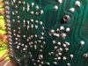
here is a pic of foil side


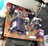
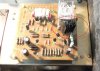
Here is a pic of component side


things of note:
1). when I saw the spark the other day, I was touching solder on R21 at the pin 1 foil. I was using a short probe, about 3/16 an inch, but I did touch the solder at the base of the probe. There may have been a scratch in the solder mask and the tip of my probe came close enough to arc. That is what blew the fuses
2). I had replaced R16 earlier. It looked like it was growing rust fur on either end. This is a 4.7k resistor. I didn’t have a 4.7ohm, so I replaced It with 2resistors in parallel that total 4.4k ohms. I planned to change out once I acquire one.
 

Attachments

  • upload_2020-8-21_17-0-27.jpeg
    upload_2020-8-21_17-0-27.jpeg
    134.8 KB · Views: 26
  • upload_2020-8-21_17-2-6.jpeg
    upload_2020-8-21_17-2-6.jpeg
    139.2 KB · Views: 26
This is the brightness of a 60W bulb in my DBT when I first powered on my SX-1050, before even popping off the top or bottom. There were no shorted components or other major failures except the main cap C2 was open:

DSCF0855.JPG

It is definitely oranger than white, so if your 60W is about that intensity you are probably ok to test on the DBT live. In my experience a quick slip of a probe is most likely to take out a semi-conductor, which then smoke resistors. I would do a quick diode test on the transistors and diodes on the -103 and -104 board looking for open or shorted junctions, then after clearing those measure voltages on the 60W DBT.
 
R16 and R15 form a voltage divider that sets the voltage on pins 9, 10, & 11 through capacitance multiplier Q8. 4.4k won't be far off but it should have the correct resistor in there for R16.
 
This is the brightness of a 60W bulb in my DBT when I first powered on my SX-1050, before even popping off the top or bottom. There were no shorted components or other major failures except the main cap C2 was open:

View attachment 1959829

It is definitely oranger than white, so if your 60W is about that intensity you are probably ok to test on the DBT live. In my experience a quick slip of a probe is most likely to take out a semi-conductor, which then smoke resistors. I would do a quick diode test on the transistors and diodes on the -103 and -104 board looking for open or shorted junctions, then after clearing those measure voltages on the 60W DBT.

do a diode test on all transistors while in circuit?
 
Yes, that will tell you if they are open or shorted junctions (power off). Looking for obvious failures on the board you might have sparked. As long as you eliminate the easily found bad ones, then you will be able to find any other problem with power on on DBT.
 
I checked all transistors. Some failed the 6 way test and when I pulled them out and tested them they passed. I ended up replacing all the smaller/ inexpensive transistors and also Q9. I didn’t replace any of the Zener diodes as I only have one each.

here are my pin readings on 60w DBT. There are no shorts. Bulb dims and after About 6 seconds, the relay engages and the bulb dims a bit more to an orange color
P1: 15.5
P2: 50.2
P3: -50.5
P4/P12: 0
P5/P6: 12.2
P7: -13
P8: -48.8
P9: -31
P10/11: 25.5
P13: 19.4
P15: 19.7
P16/17: 38.9
P18/19: 5.2
 
Those numbers look good for 60W, try 100W, if it behaves like it should, bright, then dims, then clicks, go to full mains. I think you got lucky and all it cost you was a couple of fuses and some time.
That click is probably the soft start relay coming on slow because of the DBT.
 
Those numbers look good for 60W, try 100W, if it behaves like it should, bright, then dims, then clicks, go to full mains. I think you got lucky and all it cost you was a couple of fuses and some time.
That click is probably the soft start relay coming on slow because of the DBT.
I need to buy some resistors and you mentioned how you upgraded some heatsink on transistors. Do you have recommendations based on your refurb what resistors to upgrade, not just the -103 but other pcb’s and what heatsinks to add. I have aluminum and brass bar stock. If a simple 1/2” x 1” flat or angle aluminum or brass stock will be sufficient, then I can cut it and tap the holes. If that isn’t sufficient, what would you recommend for heatsink?
 
I have some copper bar stock I bought for that purpose also, have not used it yet. Mouser heatsinks are quite expensive compared to the chinese knock-offs. Since they are not moving parts or even possible to fail I got some elsewhere.
Here is a picture of my -103 with added heatsinks (4):

DSCF0986crop.jpg

Some I had in my small heatsink drawer for years, some came (cheap) from Amazon or fleabay. Ones that fit TO-220 packages work just as well for TO-126s.
The one that really got hot was Q5 (the original is green), it was too hot to touch (upper right corner of picture).

The only resistor* I ended up replacing was R21, 100Ω, 2W, that was browning the pcb. I put in a 5W wirewound, left the legs long to get it away from the board, and had some fun adding a couple of heatsinks originally intended for TO-18 transistors:

dscf1002.jpg

Some of the smaller resistors (10Ω or so) are intended to be flameproof fusible, but not easy to pop like a regular fuse. Those I left the same to protect the unit from catching fire.
I don't see any other resistors I want/intend to change at this time. *SEE next post>
 
Last edited:
The relay driver transistor on the protection board was originally a TO-92L package, the replacement is a TO-126, so I stuck a heatsink on it, mostly just because I could. And I changed R25 to 1W and put it on standoffs to get it up and away from the board and the zener diode D5. It was also browning the pcb.

DSCF1019-2.jpg
 
Last edited:
I haven’t added any additional heatsinks yet

here are my pin readings while live - no DBT
P 1: +23.5
P 2: +75.4
P 3: -76.9
P 4 P12: 0
P 5: 7.65
P 7: -13.2
P 8: -66.7
P 9: -39.6
P10: -32.1
P13: +36
P15: +36.1
P16: +63.8
P18: +2.24

I had similar readings, so I replaced Q12. Pin 18/19 was then around 5-6 volts then I remeasured a minute later and it’s now back to 2,2 vdc.

the tuner no longer works
 
I haven’t added any additional heatsinks yet

here are my pin readings while live - no DBT
P 1: +23.5
P 2: +75.4
P 3: -76.9
P 4 P12: 0
P 5: 7.65
P 7: -13.2
P 8: -66.7
P 9: -39.6
P10: -32.1
P13: +36
P15: +36.1
P16: +63.8
P18: +2.24

I had similar readings, so I replaced Q12. Pin 18/19 was then around 5-6 volts then I remeasured a minute later and it’s now back to 2,2 vdc.

the tuner no longer works

Pin 5 & 6 feeds +13vdc to the tuner, if it is not there and correct, pin 18 and 19 will not be right either. Check pin 5, 6, that may be the problem with the tuner as well as 18 & 19.
Re Pin 18/19: Ripple killer circuit Q12 on the -103 is half of a darlington pair with Q13, replace both at the same time if pin 6 is good. If C17 is leaky it will drag down the voltage. Ripple killer output voltage is derived from the voltage at the junction of R27 & R28. Its power/current source is through R21 (100Ω). I suspect it will be good once the +13v (pin 6) is back. It was +12 on dbt earlier.
 
Last edited:
Pin 5 & 6 feeds +13vdc to the tuner, if it is not there and correct, pin 18 and 19 will not be right either. Check pin 5, 6, that may be the problem with the tuner as well as 18 & 19.
Re Pin 18/19: Ripple killer circuit Q12 on the -103 is half of a darlington pair with Q13, replace both at the same time if pin 6 is good. If C17 is leaky it will drag down the voltage. Ripple killer output voltage is derived from the voltage at the junction of R27 & R28. Its power/current source is through R21 (100Ω). I suspect it will be good once the +13v (pin 6) is back. It was +12 on dbt earlier.
I replaced Q9, 10, 11
Here are my current voltages compared to target while live. Also showing voltage on 100w DBT for reference
pin : DBT : Actual: Target
P 1: +16.2 : +23 : +24.
P 2: +52.3 : +75 : +76
P 3: - 52.7. : -77 : -76.
P5/6: +6.1: +18.9: +13
P7: -13 : -13.3 : -13
P 8: -51: -67 : -60
P 9: -27: - 38 : +30
P10/11: -22 : -32 : -25
P13/14: +22.9 : +32 : +25.
P15: +. 23.6 : +33 : +30
P16/17: + 40.7 : +63: +60
P18/19: +1.8 : +7.9 : +5.4

as you can see, I am running high ( middle numbers, target on right)

After getting the pin voltages, I shut it off. Due to the high voltages, I didn’t know if would cause damage by trying to obtain voltage readings at ECB on transistors

Note: I corrected the numbers from a previous post. I was interrupted before finishing and I accidentally hit post. The above numbers are correct.
 
Last edited:
Back
Top Bottom