• The move to the new server is done. There are some software and database maintenance updates in process. This has us passing the hat around to help out. We appreciate any donations. Seriously, even a dollar helps. The payment page may be found here - https://www.audiokarma.org/support.html

SX 626 radio side issues.

Stereoboy70

Active Member
Hello again. I got some help a while
Back with this 626. Functions working well now except the FM and AM side. I had posted that the AM/FM was not working at all but turns out it’s working. I just wasn’t turning the volume up enough to hear it. Now before anyone thinks I’m an idiot I mean I have to turn the volume ALL the way up to hear any radio signal. Phono, tape, aux are good and will sound great at low volume but when switching to stereo I have to crank the volume. If I need to realign the tuner I’ll have to get that done by someone who has the equipment. Any thoughts as to why I have to crank the volume only when playing the radio side ? Thanks in advance.
 
Register to hide this ad
Tuner seems aligned as far as pulling in stations as they correspond to the tuner dial. 104.7 a local classic rock station is right where it need to be and so is 99.1
 
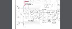
Are you getting a Stereo light on known stations? If not, check the B+ going to the tuner board to see if it's the full 12.5v. If you are getting a solid stereo light, my guess is a really dirty or worn selector switch or a broken wire(s) somewhere. The B+ to AM & FM are also switched through the selector switch.
 

Attachments

  • Screen Shot 2023-09-09 at 1.06.35 PM.png
    Screen Shot 2023-09-09 at 1.06.35 PM.png
    584.4 KB · Views: 2
Are you getting a Stereo light on known stations? If not, check the B+ going to the tuner board to see if it's the full 12.5v. If you are getting a solid stereo light, my guess is a really dirty or worn selector switch or a broken wire(s) somewhere. The B+ to AM & FM are also switched through the selector switch.
Hello. I checked the B+ to AM and it’s ok. (Around 13v) When I select FM mono or Auto I have around 1.8 v on B+
 
My service manual shows tuner board pin 4 as 1.9v going to pin 2 on IC HA1137. This come from the selector switch. There are 2 different service manuals for this receiver. This is the one I have. This corresponds with my receiver.
 

Attachments

  • IMG_0343.jpeg
    IMG_0343.jpeg
    40.2 KB · Views: 3
There's two 2.2uf coupling caps in the outputs - FM caps, C66, 67, C53 (.47uf) for the AM. Replace them. That's likely where the problem is. Use a ULK's for the replacements.
They might be the dreaded Sanyo Robin egg blue caps?
You could short another film or small e-cap across the leads and bypass them for a troubleshooting technique?
Or really crusty switches.

mmm.PNG
 
Last edited:
There's two 2.2uf coupling caps in the outputs - FM caps, C66, 67, C53 (.47uf) for the AM. Replace them. That's likely where the problem is. Use a ULK's for the replacements.
They might be the dreaded Sanyo Robin egg blue caps?
You could short another film or small e-cap across the leads and bypass them for a troubleshooting technique?
Or really crusty switches.

View attachment 2999522
Thanks. I'll Check it out tonight. I’ll do another deoxit round on the rotary switches and replace the recommended caps.
 
There's two 2.2uf coupling caps in the outputs - FM caps, C66, 67, C53 (.47uf) for the AM. Replace them. That's likely where the problem is. Use a ULK's for the replacements.
They might be the dreaded Sanyo Robin egg blue caps?
You could short another film or small e-cap across the leads and bypass them for a troubleshooting technique?
Or really crusty switches.

View attachment 2999522
My tuner board is the AWE 031 not the AWE 011. It’s different than the pic you sent
 
My tuner board is the AWE 031 not the AWE 011. It’s different than the pic you sent

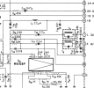
See cap C37 in the lower left corner near the chip on the schematic Zeb posted in post #9? That could also be one of the dreaded blue Sanyo caps that need to be replaced.

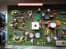
I replaced six of them in a SX-636.

IMG_20230427_140334285.jpg

IMG_20230427_142206576.jpg
 
Replaced 3 -.47 uf EC with films. No difference. Checked all cap values and they’re good. I replaced all the other caps except the ceramic disc caps. Earlier I replaced the 1137 Ic chip with a known pioneer replacement. V seem to be ok on the pins. It’s tuning good except for the volume is low even all the way up. I read somewhere to check the phono stage as well because it runs through this board ??
 
Replaced 3 -.47 uf EC with films. No difference. Checked all cap values and they’re good. I replaced all the other caps except the ceramic disc caps. Earlier I replaced the 1137 Ic chip with a known pioneer replacement. V seem to be ok on the pins. It’s tuning good except for the volume is low even all the way up. I read somewhere to check the phono stage as well because it runs through this board ??
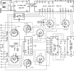
Here's where the FM signal comes in to the Head Amp Unit. It goes to switch S2, along with the phono and mic. Since the phono works we know that part is good up to the next switching coming out of the EQ unit. Check the continuity from the FM board (pins 14 & 16 in post #9) to that switch to see if it's not there.

The schematic I have has the FM output pins coming off T8 & T9 where the one in post #9 has them marked as T11 & T12.
I don't know if the attached photo is the same as your schematic.

Screenshot (199).png
 
Last edited:
Here's where the FM signal comes in to the Head Amp Unit. It goes to switch S2, along with the phono and mic. Since the phono works we know that anything past that switch is good. Check the continuity from the FM board (pins 14 & 16 in post #9) to that switch to see if it's not there.

The schematic I have has the FM output pins coming off T8 & T9 where the one in post #9 has them marked as T11 & T12.
I don't know if the attached photo is the same as your schematic.

View attachment 3001255
I’ll check this tomorrow. There are 2 different service manuals for this 626. I am using the newer one as this one corresponds to my unit. Mine has the AWE 31 tuner board not the AWE 011 board.
 
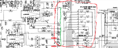
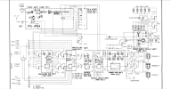
I found and downloaded that manual you're using. The schematic has a gap between where the tuner and meter drive assembly board meet and following the wires is next to impossible. Green line is in the gap. Red arrows are the FM outputs from the tuner board.

The signal goes through the meter assbly board, then down to the switch referred to in the last post.

It would be nice if you had a scope to check a good fm signal at pins 14 & 16 to see if it's there, or lost after or before that point.


Screenshot (201).png
 
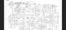
I have a scope. I know of the gap and I found another pdf of the whole thing but I’m not sure where I put it. I’ll check the FM output. Thank you.
 
believe it or not you can check the output l and right from the tuner with a digital meter set on ac/mv. if i remember correctly when tuned to a station it will be @100mv.
 
Jello
I found and downloaded that manual you're using. The schematic has a gap between where the tuner and meter drive assembly board meet and following the wires is next to impossible. Green line is in the gap. Red arrows are the FM outputs from the tuner board.

The signal goes through the meter assbly board, then down to the switch referred to in the last post.

It would be nice if you had a scope to check a good fm signal at pins 14 & 16 to see if it's there, or lost after or before that point.


One thing I noticed on the 044 EQ BOARD caps 9,10 are shown as 3.3 uf on the component list but the board schematic shows 33uf. I swapped with 3.3 and then 33 but no change.
I’ll see if I can check the signal with my scope this weekend. Thanks again.
 
I found and downloaded that manual you're using. The schematic has a gap between where the tuner and meter drive assembly board meet and following the wires is next to impossible. Green line is in the gap. Red arrows are the FM outputs from the tuner board.

The signal goes through the meter assbly board, then down to the switch referred to in the last post.

It would be nice if you had a scope to check a good fm signal at pins 14 & 16 to see if it's there, or lost after or before that point.


View attachment 3001261
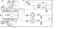
I’ve checked pins 10-11 on the HA 1142 chip and they both have 10.9 v. These pins go out to pins 14-16 on the board which are the output to the meter board pins 7-9. Still can’t seem to find to problem.
 
I’ve checked pins 10-11 on the HA 1142 chip and they both have 10.9 v. These pins go out to pins 14-16 on the board which are the output to the meter board pins 7-9. Still can’t seem to find to problem.

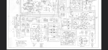
Are you tracing a signal with the scope to the meter board, then out of the meter board to switch S2? And then onwards from the switch to the inputs to the EQ board?

From there the signal goes through the EQ board to the switch assembly board.

After that it goes through the volume and balance controls, but we know that part is working.

Screenshot (209).png
 
Last edited:
Back
Top Bottom