• The move to the new server is done. There are some software and database maintenance updates in process. This has us passing the hat around to help out. We appreciate any donations. Seriously, even a dollar helps. The payment page may be found here - https://www.audiokarma.org/support.html

SX-680 Restoration Troubles

NickDeO

Active Member
Hello, AK!

Recently, I picked up a Pioneer SX-680 for $30. The guy I bought it from claimed that no sound came out due to a cracked PCB. Nice guy he was, he was even willing to open the thing up in his kitchen to show me where it was. I've since glued the cracked board and repaired the fractured traces. The darlington power packs were missing, so I replaced them as well.

Unfortunately, the DBT test declared that there's an issue somewhere else. No worries, I'm a complete novice and assumed it to be a leaky cap. I've since replaced all of the capacitors, except for the two large can caps in the power supply (waiting on 15.5mm adapters from eBay) and one very small one next to them that I forgot during my original inventory. After completely recapping the whole unit, the DBT still shines brightly as a beacon of disappointment, reminding me that our fight may be far from over... The unit powers on fine, and the lights and meters all seem to be working as they should be. However, pressing the buttons that engage the A or B outputs send the meters sky high and makes my test speaker emit a deep buzzing sound alongside the lit-up DBT. :dunno:

My next step was to look at transistors. The SX-680 has two 2SA726S PNP transistors, which show up on the troublemaker blacklist for dead sound. I removed them both to test, but nothing seems to be out of order (to the best of my limited knowledge...

Furthermore, there seems to be a few pieces missing here and there from the board. Originally, I thought somebody parted this thing out in the past, being that the power packs were gone. However, other pictures online show the same areas being unoccupied. Maybe the 680 shares the board with the SX-690?

Either way, I'm pretty stumped. Any suggestions as to what my next steps should be? I'll be able to respond to this relatively quickly and I'm happy to send pictures or perform tests with my multimeter.

This is my second big restoration, and you were all quite helpful in getting my first project completed successfully over the past few weeks. I really love this forum and I'm seriously considering a subscription!

Thanks in advance! :beerchug:
 
Register to hide this ad
Check the orientation of the two big power supply caps, if someone replaced them and put one in backwards it would cause a bright dbt. Aso check across them for a short with your meter.
 
Check the orientation of the two big power supply caps, if someone replaced them and put one in backwards it would cause a bright dbt. Aso check across them for a short with your meter.
I'm not seeing any signs of a short on the meter. It looks like they're the original caps that are still held down to the pcb with glue. Would any backwards cap cause this problem? It's not quite a full bright light as if I plugged in my shorted tester cable, but it lights the 100W bulb about halfway, if that helps.
 
Any cap tied to an unregulated dc supply might do it, but a softer glow than a full bright dbt bulb may be something else. Check for a dc offset voltage on pins 48 and 49. If there is an offset post it. If not then look at the unregulated supply voltages, they will be low, but in proportion to their full voltage, relative to each other, post the readings.
 
Any cap tied to an unregulated dc supply might do it, but a softer glow than a full bright dbt bulb may be something else. Check for a dc offset voltage on pins 48 and 49. If there is an offset post it. If not then look at the unregulated supply voltages, they will be low, but in proportion to their full voltage, relative to each other, post the readings.
Hmmm, please excuse my lack of background here... where might I find pins 48 and 49? Is that an IC? Thanks!
 
Hmmm, please excuse my lack of background here... where might I find pins 48 and 49? Is that an IC? Thanks!
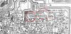
On the pcb, near the end of FU3 and FU4:
SX680pin48-49.png

EDIT: With your power meters going 'sky high' I expect there to be a high dc offset.
 
Last edited:
Update: I'm also noticing that the dbt isn't lighting up as brightly now. The only changes I've done were reinstalling the two transistors I pulled and disconnected all external inputs and speaker wires. :dunno: The meters are still maxing out at over the 30W range.
 
Update: I'm also noticing that the dbt isn't lighting up as brightly now. The only changes I've done were reinstalling the two transistors I pulled and disconnected all external inputs and speaker wires. :dunno: The meters are still maxing out at over the 30W range.
What are your power supply voltages?
 
What are your power supply voltages?
Im poking around here and since it’s all one one board, I’m not entirely sure where to find those pins... I assume the red wires are positive and the green might be negative? Again, sorry for my lack of experience here!
 
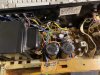
Here’s a photo of what I’m seeing — I think this portion of the main pc board is where the power supply is located
 

Attachments

  • image.jpg
    image.jpg
    144.7 KB · Views: 51
Im poking around here and since it’s all one one board, I’m not entirely sure where to find those pins... I assume the red wires are positive and the green might be negative? Again, sorry for my lack of experience here!
Don't assume, read the schematic, the only way to get more experience is dig in. :) You can do it! Most of the DC power supply connections are on the board, not wires. Don't be sorry, we all started knowing nothing. I was in Electronics Tech School at 20.

Look at this: Neets - Naval Electrical Engineering Training Series Online

The ac inputs to the power supply are pins 11 through 18, look at the upper right part of the schematic, Rows A & B, Columns 4 thru 6.
The schematic is marked with voltages near where you measure them. Don't be afraid to poke around in there, this is not your Grandfather's beloved stereo. Do not get across the ac line, that is dangerous, but the voltages and currents on the secondary side of the transformer will make arcs and sparks, and even might let out some magic smoke, if you short something out, but we've ALL done that a time or two. This is a good unit to learn on, it is not a 'valuable collectible' but is a nice vintage receiver. Enjoy the learning experience! You are building a skill few people your age will ever have nowadays. That is something to be proud of!!

I fried a transistor in my SX-1050 I am rebuilding today by putting it in with the emitter and collector swapped. I was on the dbt, making measurements as I was rebuilding the power supply, and some of the voltages were wrong. I had to troubleshoot my own repair work, and not for the first time. I had done all the ps caps, then verified the voltages were correct, first on dbt, then on full power. Transistors were next, so when I had a bad voltage I knew it had to be a transistor related problem. Looked back through my notes, took more measurments, took more notes, built up a picture in my head of where the error was and figured out I had a shorted transistor. I thought I had checked it three times when I put it in, but nope, it was installed wrong. Replaced it correctly this time, started on 120W dbt again, took more notes, this time the voltages were all correct (for on the dbt). Went to full power, checked ALL the voltages again, this time they are all good. I been doing electronics for about 50 years and I still make mistakes. We all do that and will again. Take lots of pictures and lots of notes. During that process I was constantly checking the schematic, the board layout, my notes, the datasheets, my meter readings, watching the dbt bulb, etc. Tomorrow I am going to try and hear it sing!
 
Last edited:
Don't assume, read the schematic, the only way to get more experience is dig in. :) You can do it! Most of the DC power supply connections are on the board, not wires. Don't be sorry, we all started knowing nothing. I was in Electronics Tech School at 20.

Look at this: Neets - Naval Electrical Engineering Training Series Online

The ac inputs to the power supply are pins 11 through 18, look at the upper right part of the schematic, Rows A & B, Columns 4 thru 6.
The schematic is marked with voltages near where you measure them. Don't be afraid to poke around in there, this is not your Grandfather's beloved stereo. Do not get across the ac line, that is dangerous, but the voltages and currents on the secondary side of the transformer will make arcs and sparks, and even might let out some magic smoke, if you short something out, but we've ALL done that a time or two. This is a good unit to learn on, it is not a 'valuable collectible' but is a nice vintage receiver. Enjoy the learning experience! You are building a skill few people your age will ever have nowadays. That is something to be proud of!!

I fried a transistor in my SX-1050 I am rebuilding today by putting it in with the emitter and collector swapped. I was on the dbt, making measurements as I was rebuilding the power supply, and some of the voltages were wrong. I had to troubleshoot my own repair work, and not for the first time. I had done all the ps caps, then verified the voltages were correct, first on dbt, then on full power. Transistors were next, so when I had a bad voltage I knew it had to be a transistor related problem. Looked back through my notes, took more measurments, took more notes, built up a picture in my head of where the error was and figured out I had a shorted transistor. I thought I had checked it three times when I put it in, but nope, it was installed wrong. Replaced it correctly this time, started on 120W dbt again, took more notes, this time the voltages were all correct (for on the dbt). Went to full power, checked ALL the voltages again, this time they are all good. I been doing electronics for about 50 years and I still make mistakes. We all do that and will again. Take lots of pictures and lots of notes. During that process I was constantly checking the schematic, the board layout, my notes, the datasheets, my meter readings, watching the dbt bulb, etc. Tomorrow I am going to try and hear it sing!
Thank you so much for thee resources - They'll be keeping me busy for the next few months! I also began keeping a notebook to record my measurements. I measured pins 11-18 with the red probe and held the black probe against the grounded chassis. Here are the AC voltages alongside my observations for each of these pins:

- 11: (green) 37.5 VAC
- 12: (green) 37.5 VAC - {same as pin 11}
-13: (brown and black) could not get a reading here {?}
-14: (red) 25.2 VAC
-15: (red) 25.2 VAC - {same as pin 14}
-16: (black) No reading
-17: (black) No reading - {same as pin 16}
-18: (white and black) No reading - {same as 16/16?}

I'm not entirely sure why half of the pins weren't giving me readings; maybe they're ground connections?
Thanks for the online mentourship, I'm happy to keep the hobby alive!

EDIT: I followed the black wires to the COM speaker terminals. The brown/white wires come out of the transformer and connect to these pins as well. This makes sense (4+,4-)! Also, the voltages from the green and red wires all (roughly) add up to the (roughly) 120V it gets from the wall (my outlet is measuring at 123VAC)
 
Last edited:
Thank you so much for thee resources - They'll be keeping me busy for the next few months! I also began keeping a notebook to record my measurements. I measured pins 11-18 with the red probe and held the black probe against the grounded chassis. Here are the AC voltages alongside my observations for each of these pins:

- 11: (green) 37.5 VAC
- 12: (green) 37.5 VAC - {same as pin 11}
-13: (brown and black) could not get a reading here {?}
-14: (red) 25.2 VAC
-15: (red) 25.2 VAC - {same as pin 14}
-16: (black) No reading
-17: (black) No reading - {same as pin 16}
-18: (white and black) No reading - {same as 16/16?}

I'm not entirely sure why half of the pins weren't giving me readings; maybe they're ground connections?
Best of luck with your SX-1050! Those are some pretty spectacular stereos. Also, thanks for the online mentourship, I'm happy to keep the hobby alive!

EDIT: I followed the black wires to the COM speaker terminals. The brown/white wires come out of the transformer and connect to these pins as well. This makes sense (4+,4-)! Also, the voltages from the green and red wires all (roughly) add up to the (roughly) 120V it gets from the wall (my outlet is measuring at 123VAC)
 
Thank you so much for thee resources - They'll be keeping me busy for the next few months! I also began keeping a notebook to record my measurements. I measured pins 11-18 with the red probe and held the black probe against the grounded chassis. Here are the AC voltages alongside my observations for each of these pins:

- 11: (green) 37.5 VAC
- 12: (green) 37.5 VAC - {same as pin 11}
-13: (brown and black) could not get a reading here {?}
-14: (red) 25.2 VAC
-15: (red) 25.2 VAC - {same as pin 14}
-16: (black) No reading
-17: (black) No reading - {same as pin 16}
-18: (white and black) No reading - {same as 16/16?}

I'm not entirely sure why half of the pins weren't giving me readings; maybe they're ground connections?
Thanks for the online mentourship, I'm happy to keep the hobby alive!

EDIT: I followed the black wires to the COM speaker terminals. The brown/white wires come out of the transformer and connect to these pins as well. This makes sense (4+,4-)! Also, the voltages from the green and red wires all (roughly) add up to the (roughly) 120V it gets from the wall (my outlet is measuring at 123VAC)

Look on the schematic at the connection (wire) from pin 16 back to the transformer secondary white lead, there is a ground connection right in the middle, and 17 and 18 are connected to 16 on the pcb. This is a specific connection indication, the high current return lines from the speakers are connected to the power source 'star' ground. If you look close you will see that the 'ground' side of the main filter caps are connected to the same place physically. Ground current management is very important to having low noise and low distortion. The small signal ground connections are tied together in a slightly different place and that point is connected to the star ground, so high current ground returns don't get mixed with small signal ground returns in the 'ground plane.'
 
Look on the schematic at the connection (wire) from pin 16 back to the transformer secondary white lead, there is a ground connection right in the middle, and 17 and 18 are connected to 16 on the pcb. This is a specific connection indication, the high current return lines from the speakers are connected to the power source 'star' ground. If you look close you will see that the 'ground' side of the main filter caps are connected to the same place physically. Ground current management is very important to having low noise and low distortion. The small signal ground connections are tied together in a slightly different place and that point is connected to the star ground, so high current ground returns don't get mixed with small signal ground returns in the 'ground plane.'
Ok, that would explain why the main filter caps have +30V and -30V values on the schematic. The opposite prongs on each both connect to the star ground on the PCB. In terms of cap polarity and ground wire connection to the star ground, everything seems to be in order.
 
Ok, that would explain why the main filter caps have +30V and -30V values on the schematic. The opposite prongs on each both connect to the star ground on the PCB. In terms of cap polarity and ground wire connection to the star ground, everything seems to be in order.
Yup, you're understanding it now. Most of the voltages on the schematic have chassis ground as a reference point for measurements.
 
Yup, you're understanding it now. Most of the voltages on the schematic have chassis ground as a reference point for measurements.
So what do you think might be causing this huge DC voltage offset? Would my next step be measuring the actual voltages that are listed in the schematic and comparing the values?
 
So what do you think might be causing this huge DC voltage offset? Would my next step be measuring the actual voltages that are listed in the schematic and comparing the values?
I would call it large but not huge. Q301 and Q302, both are 2SA798 5-legged dual transistors, and known troublemakers for dc offset problems as they get old. They are a differential amp (another something to learn about) and are in one package so they have the same temperature, and are supposed to be closely matched. When they get old they drift and don't match any more. Some amps have an adjustment for dc offset, this one does not. So what you do is get a bunch of 512-KSA992FBU then find gain matched ones (does your meter test transistors for hFE?) and install then with a dab of heatsink paste on the flat side and a bit of heatshrink to hold them together facing each other.
 
I would call it large but not huge. Q301 and Q302, both are 2SA798 5-legged dual transistors, and known troublemakers for dc offset problems as they get old. They are a differential amp (another something to learn about) and are in one package so they have the same temperature, and are supposed to be closely matched. When they get old they drift and don't match any more. Some amps have an adjustment for dc offset, this one does not. So what you do is get a bunch of 512-KSA992FBU then find gain matched ones (does your meter test transistors for hFE?) and install then with a dab of heatsink paste on the flat side and a bit of heatshrink to hold them together facing each other.
I’ll have to check them out, that seems pretty interesting. I’ve dealt with tubes and gain matching before, so it makes sense that solid state semiconductors would have similar properties. My multimeter is much nicer than I currently need and measures hFE either with the probes or a socket that can hold NPN and PNP transistors and a few other things. I’ll pull Q301 and Q302 tonight and see what kind of readings I get. I have a few other things to get from Digi-Key, so I suppose I might as well just replace them anyway and learn a few things about these differential amps in the meantime.

EDIT: I have hFE readings of 173/175 on Q302 and 169/168 on Q301
 
Last edited:
Back
Top Bottom