• The move to the new server is done. There are some software and database maintenance updates in process. This has us passing the hat around to help out. We appreciate any donations. Seriously, even a dollar helps. The payment page may be found here - https://www.audiokarma.org/support.html

SX-727 No power, keeps blowing fuse

Mr_Mustrd

AK Subscriber
Subscriber
Good Afternoon!

I believe I've foolishly bricked my receiver, and I'm hoping I can get a sense of direction on were to start troubleshooting to bring the 727 back from the dead. I'm brand new to working on electronics, I do have a fluke 112 DMM, hakko soldering gun, even put together a transistor tester from ebay that can tell me the HFE and the E-C-B pin layout, and also have a Dim bulb tester with a 120W bulb that the receiver is connected to whenever I turn it on.

So I've undertaken recapping the 727 and replacing known bad transistors. So far I've replaced the caps, transistors, and diodes on the power supply, AWR-011-A, and also replaced, transistors, diodes, and added the flyback diode on the protection board, AWM-027-D. Before tackling the power amp, with the receiver on aux, volume at zero, balance, bass, and treble all in the middle, no speakers connected, after 20 mins I checked the DC offset, which was somewhat stable at 0, it kept bouncing between 0 and 5, and the bias, which was steady at 20 on both channels. Music is playing great on both channels, everything appears to be normal!

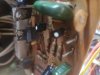
So today I wanted to tackle the power amp, AWH-011-B, replaced the caps, receiver turned on, and music was playing on both channels. Next, I replaced Q1, Q2, Q3, and Q4, I currently have the 726 installed which from what I've read the replacement are matched KSA992FBU, and this is were I think things went south, after I installed all 4 transistors and confirmed that I had the E-C-B in correctly, smoke started to rise from the area of the left trim pot. I quickly turned everything off, swapped back in the 726, and now I'm getting no lights, but no smoke, and the fuse in the back keeps pop when I replace it.

So at this point, I'm not sure what direction I should take, do I just start pulling transistors and testing them? or is there a better way to test to hopefully narrow down what the problem could be? Since I've already made a mess of things as it is I'm turning to those more experienced than I for some guidance before I make more of a mess of things than I already have. Any help would be appreciated! Thank you!
 

Attachments
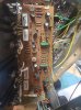
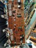
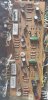
  • Power Amp AWH-011-B.jpg
    Power Amp AWH-011-B.jpg
    115.6 KB · Views: 40
Last edited:
Register to hide this ad
Next, I replaced Q1, Q2, Q3, and Q4, I currently have the 726 installed which from what I've read the replacement are matched KSA992FBU, and this is were I think things went south
Check the obvious, solder bridge on these transistors and also transistor orientation. 2SA726 appears to be bce when looking at flat face, legs pointing down, ie,
upload_2022-8-6_19-18-44.png

while the KSA992 is ecb, this means you needed to rotate the KSA992 180degrees

swapped back in the 726, and now I'm getting no lights, but no smoke, and the fuse in the back keeps pop when I replace it.
Suggest diode check/amp powered off, Q9,11,13,15(left channel) and Q10,12,14,16(R) looking for a short. Also test Q1,2,3,4. Did you replace the bias trimmers VR3,4? If all test ok then try power up with DBT (40-70W) does main fuse still blow?
Check for any stressed resistors, typically a disoloured band aqround middle. ie, what smoked?
 
Last edited:
Check the obvious, solder bridge on these transistors and also transistor orientation. 2SA726 appears to be bce when looking at flat face, legs pointing down, ie,
View attachment 2632752

while the KSA992 is ecb, this means you needed to rotate the KSA992 180degrees


Suggest diode check/amp powered off, Q9,11,13,15(left channel) and Q10,12,14,16(R) looking for a short. Also test Q1,2,3,4. Did you replace the bias trimmers VR3,4? If all test ok then try power up with DBT (40-70W) does main fuse still blow?
Check for any stressed resistors, typically a disoloured band aqround middle. ie, what smoked?

Thank you! I'll check those transistors and confirm the orientation is correct and get back to you. Just to make sure, I'll be testing them out of circuit correct?

I do have replacement trimmers on the way because I thought the one on the edge was smoking, I've also ordered matched 992 from peace.love.music from ebay because the 992 from mouser are on back order.

I did have a replacement trimmer, so I pulled the old bias trimmers, checked the resistance and adjusted the new trimmers to match the old ones, but when I turned the 727 on there was still smoke, put the old ones back in, now theres no power.
 
Maybe it can help you to compare, here is a picture from my working Power Amp Board AWH-011. On your picture it seems to me, that the resistor R39 has got some heat marking.

20220616_125544.jpg
 
I'll check those transistors and confirm the orientation is correct and get back to you. Just to make sure, I'll be testing them out of circuit correct?
As a first step, I'd test them in circuit, you are looking for a short, if they test bad then remove and retest.

I've also ordered matched 992 from peace.love.music from ebay because the 992 from mouser are on back order.
Mouser has 120000+ KSA992 depending on tape or loose... order 20-50 and use your tester to hfe and Vbe match.

I did have a replacement trimmer, so I pulled the old bias trimmers, checked the resistance and adjusted the new trimmers to match the old ones, but when I turned the 727 on there was still smoke, put the old ones back in, now theres no power.
Better to set the new trimmer to zero resistance before DBT power up

On your picture it seems to me, that the resistor R39 has got some heat marking.
Excellent pick up

Orientation of Q2 and Q3 look wrong.
 
I marked the parts on your board where I see a difference compared to my board and you should recheck again, especially the transistor pinout.

And after 40 years I always replace all trimmer on the power amps with new ones.

Power Amp AWH-011-B recheck transitor pin out.jpg
 
Good Morning!

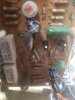
I actually ended up pulling all of the transistors and testing them out of circuit and they all are giving me a reading, but I found out that my transistor tester kit I purchased from eBay was giving me the wrong pin outs layout! any recommendation on a replacement? So I only used it to test the transistor, I did write down the Hfe and Mv ratings of each transistor, and then placed them back onto the board the way I found them. I also hopefully fixed the orientation of Q2 and Q3, I've attached a photo of what the board looks like now.

I didn't remove the 4 output transistors attached to the heatsink, but I did test them for resistance and they are all showing about 100. The charred resistor I did remove, and get a reading, but its safe to assume this would need to be replaced, what would be a good replacement?

I did find a 60w incandescent bulb, had to end up going to batteries bulbs and plus. But, tried to fire up the received with a new fuse, and it's still popping, but no smoke! which is great, but no power. I do have replacements for all of the transistors except for the 4 output transistors, should I replace those? or order the new resistor and put that in?

Thank you for all the help!!
 

Attachments

  • Power amp Left.jpg
    Power amp Left.jpg
    69.2 KB · Views: 13
  • Power amp Right.jpg
    Power amp Right.jpg
    58.3 KB · Views: 13
Last edited:
Can you post a few screenshots?

Attached is the picture of me testing the KSA992, according to the spec sheet it should be E C B, but the tester is saying it's B E C. Since I don't know what I'm doing, it's very possible I'm misreading it.
 

Attachments

  • Ebay Tester.jpg
    Ebay Tester.jpg
    83.2 KB · Views: 36
  • 992.jpg
    992.jpg
    61.5 KB · Views: 29
Attached is the picture of me testing the KSA992, according to the spec sheet it should be E C B, but the tester is saying it's B E C. Since I don't know what I'm doing, it's very possible I'm misreading it.
The tester is good. You need to correspond the numbers on the tester to the readout screen.
The legs in sequence are 2-3-1.
Move the transistor over one slot to the left and it will read ECB
 
That’s a very helpful way for testing a Transistor:

https://audiokarma.org/forums/index...-transistor-testing-basics.43186/#post-432830

I use this cheap tester and it works very well

LCR tester mega 328 (my every time saver if I need to identify the pin out)

Look for LCR-T4 Mega328 Transistor Tester

https://www.ebay.de/itm/354075579169?hash=item52708c9321:g:Ss4AAOSw7cdijMs-

I'll read that thread, thank you! The one I bought does state its the Mega 328, I was misreading it. But every transistor that I pulled did get a reading using that tester. I think at this point I have a transistor in backwards? I'm pretty sure I have them in right, but I'll take another look at it.
 
Attached is the picture of me testing the KSA992, according to the spec sheet it should be E C B, but the tester is saying it's B E C. Since I don't know what I'm doing, it's very possible I'm misreading it.

Sorry if I have a big laugh, but your problem is between the headset. :beerchug:

The SA992 pinout is ECB, so you are correct with this.
BUT on your tester, you ignored the numbers for the little slots shown on the board above the top row.

It looks that your tester is similar to mine and the corresponding numbers are from left to right on top and bottom row

123 – 1111

That gives you the chance with bigger parts like resistors, to use the right side for the wider gap.

What I see on your picture with the SA992, you started with the left pin in slot 2 followed by slot 3 and 1

That’s the reason why you get on the display 2=E, 3= C, 1 = B.
All perfectly correct indicated according to the selected slot.
 
Sorry if I have a big laugh, but your problem is between the headset. :beerchug:

The SA992 pinout is ECB, so you are correct with this.
BUT on your tester, you ignored the numbers for the little slots shown on the board above the top row.

It looks that your tester is similar to mine and the corresponding numbers are from left to right on top and bottom row

123 – 1111

That gives you the chance with bigger parts like resistors, to use the right side for the wider gap.

What I see on your picture with the SA992, you started with the left pin in slot 2 followed by slot 3 and 1

That’s the reason why you get on the display 2=E, 3= C, 1 = B.
All perfectly correct indicated according to the selected slot.

Thank you! This is a learning experience for me and you're correct the problem is with me, I see that you've been talking to my wife! ;)

It is reassuring that my tester wasn't leading me astray, I'm just not reading it correctly. I'm going to review what I've put in and double check all transistors that I've touched and make sure that everything is in the correct way.
 
You are not the first with wrong pin out and it will be not your last time. :lurk:
It has happened to everyone, and always remember, the self-induced problem’s are the hardest to find.
 
I did correct Q3 and Q4, also corrected Q12. I've posted pictures of the transistors at an angle so that anyone reviewing it can see how I have pins in. I've tripled checked everything and they are all in correctly, but the receiver is still blowing a fuse.

For the burnt up resistor I'll order a new one, along with new 250V 3A fast acting fuses, and trimmers 652-3386F-1-502LF and 652-3386F-1-222LF from mouser, would 279-CFR50J100R Carbon Film Resistor Through Hole 100Ohm 1/2W 1200PPM be a suitable replacement for the burnt resister on R39?

Thank you everyone for all your help! Even though I haven't made much progress I've still learned a lot and appreciate everyone's help!
 

Attachments

  • Power Amp Top left.jpg
    Power Amp Top left.jpg
    68.7 KB · Views: 11
  • Power Amp Top left angled.jpg
    Power Amp Top left angled.jpg
    72.1 KB · Views: 14
  • Power Amp bottom right angled.jpg
    Power Amp bottom right angled.jpg
    67.9 KB · Views: 11
  • Power Amp Bottom right.jpg
    Power Amp Bottom right.jpg
    71.5 KB · Views: 10
As long as you are unsure, that the problem is fixed, you should only start und run the unit on DBT. Otherwise you are blowing the fuse one by one.

Hope that one of the real experts joins in.

Your pictures are not the best. Can you get another one with a macro function?

Please give us an answer to...

1. Do you have the unit on a DBT and to you know how to use the DBT.

2. Which fuse keeps blowing and does it still blow when you use the DBT between wall socket and receiver?

3. What is the rating on the replacement fuse that you are using?

4. What version is your SX-727, there should be a round label on the rear panel reading either KUW or FW.

5. Last question, did you change some lights at the dial scale or the meters? If yes, what did you use for a replacement?
 
As long as you are unsure, that the problem is fixed, you should only start und run the unit on DBT. Otherwise you are blowing the fuse one by one.

Hope that one of the real experts joins in.

Your pictures are not the best. Can you get another one with a macro function?

You're correct, the pictures are not the best, unfortuanlty my phone does not have a macro function, I'm using a galaxy note 9, so the zoom feature gets blurry at best. I took another top down view, tried make sure it's a clear as possible.

1. Do you have the unit on a DBT and to you know how to use the DBT.

I built one based off of the instructions found here on audiokarma, I've kept the receiver connect to the DBT and not the wall when turning on, I've uploaded a picture of the wiring.

2. Which fuse keeps blowing and does it still blow when you use the DBT between wall socket and receiver?

3. What is the rating on the replacement fuse that you are using?

The fuses that was using was 250V 4amp purchased from my local home depot, I've ordered more fuses from mouser, which are 250V 3A Fast Acting 576-0312003.MXP.

The fuse that keeps blowing is the one screwed into the back of the receiver. The 3 fuses located inside the receiver appear to be unharmed. Since I've always kept it plugged into the DBT I haven't tried directly into the wall, before the receiver was able to power on while be connected to the DBT.

4. What version is your SX-727, there should be a round label on the rear panel reading either KUW or FW.

Mine is showing as KUW

5. Last question, did you change some lights at the dial scale or the meters? If yes, what did you use for a replacement?

When I first bought this receiver, this has the LED lights, I didn't like how they look and preferred using light bulbs, so I contacted dgwojo who provided me replacements, the bulbs are 8v fuse style.
 

Attachments

  • Power Amp.jpg
    Power Amp.jpg
    95 KB · Views: 14
  • DBT.jpg
    DBT.jpg
    66.2 KB · Views: 11
  • DBT Guts.jpg
    DBT Guts.jpg
    48.7 KB · Views: 14
First off all, I’m not an expert, rather a newbie who starter repairing old receivers two years ago. So I try to give you some help, with my limited experience and you can follow my words on your own risk. Second, I’m not an English native speaker, so my explanation might not always be the best and you have to use common sense.

Starting with the DBT. From your picture it is hard to follow the wiring so I give you another link to compare how it is done properly.

http://www.geek-tips.com/2015/11/22/dim-bulb-tester/

What it does is quite simple. The important piece is the lamp after the switch sitting in the hot line between the wall socket and the socket where your receiver is plugged in (on the picture the “device under test”). The neutral and ground can go direct from the receiver back to the wall socket.

If this setup is correct, the bulb works as an extra load BEFORE the power goes into your receiver and will blow something like the fuse or transistor.

On a unit without a short you should see immediately after power on and with a 60W bulb, the bulb will go on for max. 2-3 seconds, that’s the time the big capacitor need to charge and then it goes dim if everything is working fine. If the bulb stays bright, meaning there is a bigger power demand, indicating some problems like a short, you should switch off the unit right away to prevent further damage.

Since you always have a blown fuse, can only mean, your wiring on the DBT is wrong or you are waiting to long with a bright bulb. You better recheck the correct function of the DBT, there should be as well some information on youtube.

Next part is your bulb replacements. What did you use right now? 8v-AC LED in fuse style or standard fuse style 8v incandescent light?

A few months ago we worked hard on a similar issue until the thread starter found out, that he had mistakenly placed a fuse instead of one of the 8V lamps!
 
Last edited:
Back
Top Bottom