• The move to the new server is done. There are some software and database maintenance updates in process. This has us passing the hat around to help out. We appreciate any donations. Seriously, even a dollar helps. The payment page may be found here - https://www.audiokarma.org/support.html

SX-727 No power, keeps blowing fuse

Get everything on the amp board oriented correctly. Don't fire it up yet. Pull and test each of the output transistors, and lift one leg of each of the emitter resistors. Test individually. Emitter resistors are the big ceramic 0.5Ω 5W.

You can pull each output and test them on your tester. They need to be out of circuit to test effectively. Cut some old cap leads, insert these into the 1-2-3 holes in your tester, clamp and then connect and use test leads with clips to connect to the transistor itself and the tester. I'm betting you've got a bad output transistor and/or one of the emitter resistors went bad. Put on DBT and power up without the output transistors. If it dims down after 2-3 seconds you've probably got at least one output transistor bad. Install output transistors in one channel and retest on the DBT. If ok, pull them and put the other pair in. Retest. If either pair is bad replace all 4.

If your Round Label is missing, look on the back panel for a voltage selector. If no Voltage selector it's a KUT
 
Last edited:
First off all, I’m not an expert, rather a newbie who starter repairing old receivers two years ago. So I try to give you some help, with my limited experience and you can follow my words on your own risk. Second, I’m not an English native speaker, so my explanation might not always be the best and you have to use common sense.

Starting with the DBT. From your picture it is hard to follow the wiring so I give you another link to compare how it is done properly.

http://www.geek-tips.com/2015/11/22/dim-bulb-tester/

What it does is quite simple. The important piece is the lamp after the switch sitting in the hot line between the wall socket and the socket where your receiver is plugged in (on the picture the “device under test”). The neutral and ground can go direct from the receiver back to the wall socket.

If this setup is correct, the bulb works as an extra load BEFORE the power goes into your receiver and will blow something like the fuse or transistor.

On a unit without a short you should see immediately after power on and with a 60W bulb, the bulb will go on for max. 2-3 seconds, that’s the time the big capacitor need to charge and then it goes dim if everything is working fine. If the bulb stays bright, meaning there is a bigger power demand, indicating some problems like a short, you should switch off the unit right away to prevent further damage.

Since you always have a blown fuse, can only mean, your wiring on the DBT is wrong or you are waiting to long with a bright bulb. You better recheck the correct function of the DBT, there should be as well some information on you tube.

Next part is your bulb replacements. What did you use right now? 8v-AC LED in fuse style or standard fuse style 8v incandescent light?

A few months ago we worked hard on a similar use until the thread starter found out, that he had mistakenly placed a fuse instead of one of the 8V lamps!

I appreciate the extra eyes no matter what your experience level is at! You've been extremely helpful so far, and this is a learning experience for me. I will review the link you sent me, since I don't have any more fuses I won't be tempted to turn on the receiver :D There is a good chance my DBT is wired wrong and that needs to be fixed first thing.

As for the light bulbs, I replaced them when I first got the receiver several months ago and I used what was sent to me, which was the standard fuse style 8v incandescent light bulbs that fellow audiokarma user dgwojo, www.dgwojo.com, from what I've read hes the guy to get new bulbs that won't ruin the receiver.
 
Get everything on the amp board oriented correctly. Don't fire it up yet. Pull and test each of the output transistors, and lift one leg of each of the emitter resistors. Test individually. Emitter resistors are the big ceramic 0.5Ω 5W.

You can pull each output and test them on your tester. They need to be out of circuit to test effectively. Cut some old cap leads, insert these into the 1-2-3 holes in your tester, clamp and then connect and use test leads with clips to connect to the transistor itself and the tester. I'm betting you've got a bad output transistor and/or one of the emitter resistors went bad. Put on DBT and power up without the output transistors. If it dims down after 2-3 seconds you've probably got at least one output transistor bad. Install output transistors in one channel and retest on the DBT. If ok, pull them and put the other pair in. Retest. If either pair is bad replace all 4.

If your Round Label is missing, look on the back panel for a voltage selector. If no Voltage selector it's a KUT


Thank you Larry! Before I bought my SX 727, it was your posts that sold me on it :beerchug:

I just want to clarify, when you refer to the output transistors are you referring to the big 4 that are attached to the heatsink? Which are Q14, Q16, Q15, and Q13? If so, what is the best way to remove them without destroying the wire wrap?

Great advice on the tester, I never thought sticking leads in the slots prior, that will make things much easier in testing. I will check the emitter resistors and recheck the rest of the transistors and get back to you. I did pull them prior and my tester was giving a reading for them all, but if needed I do have replacements for all the transistors except for the big 4 attached to the heatsink. Also pa_220 has pointed out that my DBT needs to be fixed so that's the first thing to tackle, get that working correctly, and then go from there.

On order I have new fuses, trimmers, and a replacement resistor for the one that is burnt.
 
Look on the outside of the output transistors (yes Q13-14-15-16) where the writing is on them. Undo the two screws, and they pull straight out from their socket. Note that the pins are offset from center so they only go in one way. The pins will be marked with an E or a B on the inner side of the case next to the pins (E=Emitter, B=Base). The case itself is the collector. The wire wraps are from the boards to the sockets. DON'T MESS with them!
 
Look on the outside of the output transistors (yes Q13-14-15-16) where the writing is on them. Undo the two screws, and they pull straight out from their socket. Note that the pins are offset from center so they only go in one way. The pins will be marked with an E or a B on the inner side of the case next to the pins (E=Emitter, B=Base). The case itself is the collector. The wire wraps are from the boards to the sockets. DON'T MESS with them!

Thank you! Heard! Didn't feel messing with the wire wraps was a good idea anyways. 'll get them out and test them.
 
Thanks @larryderouin, I was hoping that we could count on your help here!
Larry I always wanted to ask you, what is the best replacement if one of the SV-3A goes bad?

One more basic information for @Mr_Mustrd
Are you aware that the board layouts printed in the Pioneer Service Manual always show only the foil side with the parts and pin out information to give one a help when looking for and desoldering parts. The information on the part side is already printed on the top of the boards part side.

But I personal prefer a paper print for both sides. To get the top I use a snipping tool, copy it two times to MS Word and then flip one copy horizontal with the Word tools to get the top layout. The only “little problem” are the mirrored letters and numbers for the part side print.

Here is one example for you
 

Attachments

One more advice from my as a newbie.
Make lots of good quality pictures or put down some notes from every part BEFORE you remove it. Even with the big output Transistors.

It looks very easy at the beginning, but the first time I wanted to installed them back to the heatsink, without the preinstalled information, it took me some time to have the correct transistor in the right position.
For the experts it's logic and common business, but better be prepared as newbie.

And get some new heat grease and maybe new TO 3 glimmer disc before the reinstall.
 
Pioneer originally used a transparent spray on the heatsinks at the transistors that sufficed in lieu of Heatsink grease and Mica insulators. It's single use so when you put them back in you'll need a TO-3/TO-204 insulator per transistor and heatsink grease. Don't make the mistake 99% of newbie's make. Like Brylcreem, "A little dab'll do ya". a very light TRANSLUCENT layer on both sides is sufficient. All it needs to do is to fill microscopic pits and grooves in the metal. This aids in heat shedding. Any more than that and you get into actually insulating the Transistor from the heatsink (BAD JU-JU!). A little dab (a little smaller than a green pea.) on tip your index finger, rub against your thumb, then put an insulator between finger and thumb and hit 100% of the insulator. If any squeezes out (other than a little here and there) you used too much.

Clean off the original stuff around the transistor mounts with Acetone on a cloth in an open area (or under an exhaust hood or next to an outside exhaust fan).

TO-3 Mica Insulator: https://www.mouser.com/ProductDetail/Keystone-Electronics/4636?qs=Mn60vILZNNZyRxqVWcek6g==

Heatsink grease: https://www.mouser.com/ProductDetail/Chemtronics/CW7250?qs=IjV9znPSaN2bVYU6q2%2By8g==
 
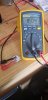
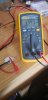
Thank you @pa_200! This is really good advice, I remember reading your other post were you went into further detail regarding how you made your own foil side printouts, and I can see how helpful that will be, I plan on making some as well. I also fixed my dim bulb tester! The light bulb is now lighting up when I short the receiver side of the plug, I posted a picture below. I had the wiring wrong so I bought a new outlet and started from scratch.

Look on the outside of the output transistors (yes Q13-14-15-16) where the writing is on them. Undo the two screws, and they pull straight out from their socket. Note that the pins are offset from center so they only go in one way. The pins will be marked with an E or a B on the inner side of the case next to the pins (E=Emitter, B=Base). The case itself is the collector. The wire wraps are from the boards to the sockets. DON'T MESS with them!

I pulled all four output transistors out, the wire wrap was not destroyed, they just pulled straight out like you said. I tested them using my multimeter by connecting the negative to the emitter pin and then the positive to the base, and then swapped them, I got a reading both ways. Were as with the other 3 transistors, one way I got a reading and then reversed I got OL which should indicate that three of them are good and the last one is shorted? I also tested all four emitter resistors by de-soldering one leg to pull them out of circuit, they all tested around .7Ω to .8Ω, which should be okay? but I can order new ones and replace them since they are already halfway out.

So it looks like my problem is the output transistor is shot which is causing the fuse to pop, along with making sure every other transistor is in correctly. I'll hold off on placing an mouser order for replacements until I get a confirmation.

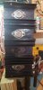
The mouser order will be for 2 863-MJ21194G and 2 863-MJ21193G to replace the 4 output transistors, along with 4 534-4636 mica insulators. I already have Wakefield 120, will be sufficient for the heatsink? or should I get the 5168-7250 heat shield grease as you suggested? and finally 4 280-CR5-0.5-RC 0.5Ω wirewound resistors, or should I just leave the original in there?

The above order will run about $70 bucks which is an expensive lesson but one that I was glad to learn! Thank you @pa_200 and @larryderouin for taking the time out of your day to help out! I really appreciate it!
 

Attachments

  • DBT working!.jpg
    DBT working!.jpg
    48.3 KB · Views: 14
  • output test 2.jpg
    output test 2.jpg
    64.7 KB · Views: 16
  • Output test 1.jpg
    Output test 1.jpg
    67.1 KB · Views: 17
  • Output Trans.jpg
    Output Trans.jpg
    49.8 KB · Views: 14
  • Heatsink.jpg
    Heatsink.jpg
    67.7 KB · Views: 15
Last edited:
Couple of things............

1.) The 0.7Ω to 0.8Ω readings probably include the resistance from the leads and meter. Touch the leads together before you test anything and note the reading. Then subtract that number from your test readings on components. Your emitter resistors are probably fine and your meter most likely has a resistance in the leads of 0.2Ω to 0.3Ω.
If so no need to replace the emitter resistors.

2.) Looks like You've got a bad output transistor. Verify it with a 6way test ........ post 1 thru 11. https://audiokarma.org/forums/index.php?threads/bipolar-junction-transistor-testing-basics.43186/ Do all 4. Possibility exists that something upstream killed the transistor, so check all the transistors, caps and resistors on the amp board before installing the new output's. No troublemaker transistors on the amp board that I can recall (top ten most wanted list), but that doesn't preclude an outlier. IIRC there are a couple of 2sa725's on the AF UNIT Board. pre-emptively replace those.

3.) the mj21193G & 94G are fine. If not in stock use the 95G and 96G. Essentially the same transistor the spec's are so close.

4.) The Wakefield grease is good. Use it. I prefer the Mica insulators, but some guys like Silicone (Sil-Pads) insulators. More expensive, so they have to work better, right?!

5.) Protection circuit board. Install a 1n4004 diode between pins 14 and 15. Cathode to pin 15. This protects Q7?(I'm not looking at the schematics so I'm spitballing) the last transistor before the pins, from reverse voltage when you shut down and the field collaspes in the relay coil. PIONEER installed this diode in later models, and we advocate the upgrade.

6.) Protection timing on start up is 4 to 7 seconds. If it's LOWER than that (count seconds from when you throw power switch to when relay trips (clicks)) you need to change the timing cap on the protection board. This will be part of your restore project.
 
Last edited:
Have you done the “six-way-transistor test” I have linked in post 12 and Larry asked above as No. 2
How are the results?
https://audiokarma.org/forums/index...-transistor-testing-basics.43186/#post-432830

Very important!! It works only on your DMM if you set it to the Diode Test Function!
It will not work if your DMM is set to Resistance / Ohm.

If you did the testing in the described way and the parts are good, disregard my question.
 
Last edited:
2.) Looks like You've got a bad output transistor. Verify it with a 6way test ........ post 1 thru 11. https://audiokarma.org/forums/index.php?threads/bipolar-junction-transistor-testing-basics.43186/ Do all 4. Possibility exists that something upstream killed the transistor, so check all the transistors, caps and resistors on the amp board before installing the new output's. No troublemaker transistors on the amp board that I can recall (top ten most wanted list), but that doesn't preclude an outlier. IIRC there are a couple of 2sa725's on the AF UNIT Board. pre-emptively replace those.

Pulled all four, set my DMM to Diode, and below are the results:

Q14 which is 2SD388 NPN
Negative to Base - Positive to Collector = OL
Negative to Base - Positive to Emitter = OL
Positive to Base - Negative to Collector = .447
Positive to Base - Negative to Emitter = .476
Negative to Emitter - Positive to Collector= OL
Positive to Emitter - Negative to Collector = OL

Q16 which is 2SA649 PNP
Negative to Base - Positive to Collector = OL
Negative to Base - Positive to Emitter = .554
Positive to Base - Negative to Collector = OL
Positive to Base - Negative to Emitter = OL
Negative to Emitter - Positive to Collector= OL
Positive to Emitter - Negative to Collector = OL

Q15 which is 2SA649 PNP
Negative to Base - Positive to Collector = .500
Negative to Base - Positive to Emitter = .554
Positive to Base - Negative to Collector = 1.161
Positive to Base - Negative to Emitter = 1.143
Negative to Emitter - Positive to Collector= .0001 continuous beep
Positive to Emitter - Negative to Collector = .0001 continuous beep

Q13 which is 2SD388 NPN
Negative to Base - Positive to Collector = OL
Negative to Base - Positive to Emitter = 1.160
Positive to Base - Negative to Collector = OL
Positive to Base - Negative to Emitter = .386
Negative to Emitter - Positive to Collector= OL
Positive to Emitter - Negative to Collector = OL

So from what I read from the thread you and @pa_200 posted, the only transistor that is working is Q16.

When I first purchased this receiver one of the first things I did was replace which I believe were 2sa725 or maybe the 726 on the AF board and I did replace those with the 992. But the plan is to replace all the capacitors on all boards, I plan on only replacing the capacitors on the tuner, and leave the rest untouched for the tuner.

3.) the mj21193G & 94G are fine. If not in stock use the 95G and 96G. Essentially the same transistor the spec's are so close.

Was able to order the MJ21193G and 94G. Should be here Monday. Do I have to worry about matching these?

4.) The Wakefield grease is good. Use it. I prefer the Mica insulators, but some guys like Silicone (Sil-Pads) insulators. More expensive, so they have to work better, right?!

Sounds good, I'll use the Wakefield grease like you said, no more than a pea sized, less is better, the mica insulators will be here Monday. It sound very similar to applying thermal paste when installed a CPU on a computer I built.

5.) Protection circuit board. Install a 1n4004 diode between pins 14 and 15. Cathode to pin 15. This protects Q7?(I'm not looking at the schematics so I'm spitballing) the last transistor before the pins, from reverse voltage when you shut down and the field collaspes in the relay coil. PIONEER installed this diode in later models, and we advocate the upgrade.

6.) Protection timing on start up is 4 to 7 seconds. If it's LOWER than that (count seconds from when you throw power switch to when relay trips (clicks)) you need to change the timing cap on the protection board. This will be part of your restore project.

Before I started on the power amp I replaced all of the capacitors on the protection board and installed the flyback diode on pins 14 and 15. I let the receiver warm up for 10 mins and the DC offset kept shifting from 0 to .05. and I set the bias to 20 which stayed solid on. Which at the time I thought I was good to work on the power amp which lead me to my downfall.

 
Have you done the “six-way-transistor test” I have linked in post 12 and Larry asked above as No. 2
How are the results?
https://audiokarma.org/forums/index...-transistor-testing-basics.43186/#post-432830

Very important!! It works only on your DMM if you set it to the Diode Test Function!
It will not work if your DMM is set to Resistance / Ohm.

If you did the testing in the described way and the parts are good, disregard my question.

Was not testing it correctly, thank you for the links!
 
As a help for you and to compare with your bad transistors readings, here are my results from the 4 good output transistors. The only difference to mine, the factory installed NPN was a 2SD323 instead of your SD388 for the NPN and 2SA649 as PNP.


DMM set to Diode test, and below are the results:

Black lead = Negative, Red lead = Positiv

Q14 which is a good 2SD323 NPN
Black to Base - Red to Collector = OL
Black to Base - Red to Emitter = OL
Red to Base - Black to Collector = .599
Red to Base - Black to Emitter = .545
Black to Emitter - Red to Collector= OL
Red to Emitter - Black to Collector = OL

Q16 which is a good 2SA649 PNP
Black to Base - Red to Collector = .450
Black to Base - Red to Emitter = .580
Red to Base - Black to Collector = OL
Red to Base - Black to Emitter = OL
Black to Emitter - Red to Collector= OL
Red to Emitter - Black to Collector = OL

Q15 which is a good 2SA649 PNP
Black to Base - Red to Collector = .505
Black to Base - Red to Emitter = .506
Red to Base - Black to Collector = OL
Red to Base - Black to Emitter = OL
Black to Emitter - Red to Collector= OL
Red to Emitter - Black to Collector = OL

Q13 which is a good 2SD323 NPN
Black to Base - Red to Collector = OL
Black to Base - Red to Emitter = OL
Red to Base - Black to Collector = .639
Red to Base - Black to Emitter = .755
Black to Emitter - Red to Collector= OL
Red to Emitter - Black to Collector = OL


To make this test easer (or foolproof) for me, I collected all the relevant information from AK and made a small 3-page-paper the write down my results on the last page.

For every one, feel free to keep a copy of my little “memory support”
 

Attachments

Last edited:
I hope @larryderouin agrees, don’t reinstall the new output transistors before you hat a good DBT test.
All power supply voltages must be good, as well the protection board and the power amp.
I wouldn't reinstall the outputs as longe as your DBT stays bright after Power up. See Post #21

I would wait for Larry’s reply before you continue.

Will do! Thank you!

I did receive the replacement trimmers, how do I set the resistance to zero? Which pin do I use to set it to zero?
 
All four work in the same direction. Can you post a link or picture which one you have ordered?

If you can wait with your first power up test, I will try to write a little summary about my “fail safe for beginner test setup” for the bias and dc 0ffset adjustment.
 
All four work in the same direction. Can you post a link or picture which one you have ordered?

If you can wait with your first power up test, I will try to write a little summary about my “fail safe for beginner test setup” for the bias and dc 0ffset adjustment.

Attached are the trimmers. Thank you!
 

Attachments

  • 20220812_113308.jpg
    20220812_113308.jpg
    55.9 KB · Views: 20
  • 20220812_113224.jpg
    20220812_113224.jpg
    66.4 KB · Views: 16
Back
Top Bottom