

You are using an out of date browser. It may not display this or other websites correctly.
You should upgrade or use an alternative browser.
You should upgrade or use an alternative browser.
SX-737 power amp AWH-033 issue, blown transistors
One question about the function on the power supply board AWR-057. Before starting the work on that board I took all ac and dc voltages with the original parts. Every voltage looked fine nothing way off.
Measured every exchange part and there was only the c11 way off. All other caps were in limit and had a very low ESR, all around 0.xx. Very surprising after 40 years.
Only the c11 cap 220µf/16v has been down to 15µf and a vlos of 26%.
What I would like to understand, I didn’t see any remarkable change at the voltages with the new parts compared to the old ones with that very low c11.
Pin 12/13 had -13.2 vdc before and -13.3 vdc afterwards.
Measured every exchange part and there was only the c11 way off. All other caps were in limit and had a very low ESR, all around 0.xx. Very surprising after 40 years.
Only the c11 cap 220µf/16v has been down to 15µf and a vlos of 26%.
What I would like to understand, I didn’t see any remarkable change at the voltages with the new parts compared to the old ones with that very low c11.
Pin 12/13 had -13.2 vdc before and -13.3 vdc afterwards.

merlynski
Curmudgeon Electronicist
One question about the function on the power supply board AWR-057. Before starting the work on that board I took all ac and dc voltages with the original parts. Every voltage looked fine nothing way off.
Measured every exchange part and there was only the c11 way off. All other caps were in limit and had a very low ESR, all around 0.xx. Very surprising after 40 years.
Only the c11 cap 220µf/16v has been down to 15µf and a vlos of 26%.
What I would like to understand, I didn’t see any remarkable change at the voltages with the new parts compared to the old ones with that very low c11.
Pin 12/13 had -13.2 vdc before and -13.3 vdc afterwards.
The DC voltage at pins 12/13 is strongly controlled by the 13v zener diode D8, and the current through R2, 1kΩ 1W. Unless the load draws enough current to diminish the current through D8 (causing excessive voltage drop across R2), D8 will stay in regulation at its rated voltage. By their very nature zener diodes generate noise, both from the 'zener junction avalanche' and the variation of the current through them as they regulate their voltage. C11 is there to control that noise, smoothing the voltage variations, both high frequency (avalanche) and regulation (load varied) so it is a large value. It does not affect the DC voltage much that you will see with a DMM on a 20vdc range. To see the intended effect of C11 you would need to look at those pins with an oscilloscope, ac coupled, on a millivolt range, then remove it and remeasure. Those -13vdc supply lines feed the power amp DC offset circuit and the phono (RIAA) equalizer amp, neither of which (IHMO) will be high current draws, but may be sensitive to broadband noise. The equalizer pcb (AWF-011) has a 220µf cap (C18) on that end of the supply line, and the power amp has a high input impedance drawing from that supply, so 15µf was probably enough to not be a problem. If you still have the cap you removed look and see if it is not labeled 16µf. Pioneer may have increased the value as an improvement to the phono noise floor. Just guessing, but I have seen that kind of thing in other threads and schematics.
merlynski
Curmudgeon Electronicist
It was a bad cap then, that is why old electrolytic caps need replaced.I have still all the old parts, every single one from every board.
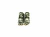
The left cap was the c11 and the right one was c16.
View attachment 1623827
Yes you are absolutely right.It was a bad cap then, that is why old electrolytic caps need replaced.
Now I just hope to find a way to improve the sound, it’s still a bit flat compared to my SX-828.
merlynski
Curmudgeon Electronicist
Are you saying with the same input source and the same speakers, your SX-737 has less bass response?
Is it the same in both channels? Does the volume level change the response?
The next cap in the signal path I would look at is the Control Amp (AWG-030) input cap C1, C2. My schematic shows them as 1µf, 25v. That is the next lowest value cap in the direct signal path (for Aux input). The other caps in series with the signal path are 4.7µf (C9, C10, C19 & C20) and 2.2µf (C23, C24). Check C29, 100µf, 35v, it is the on board + voltage supply filter cap. I hesitate to suggest changing values in fear of unintended consequences, but putting 2.2µf in place of 1µf for C1, C2 might help.
Is it the same in both channels? Does the volume level change the response?
The next cap in the signal path I would look at is the Control Amp (AWG-030) input cap C1, C2. My schematic shows them as 1µf, 25v. That is the next lowest value cap in the direct signal path (for Aux input). The other caps in series with the signal path are 4.7µf (C9, C10, C19 & C20) and 2.2µf (C23, C24). Check C29, 100µf, 35v, it is the on board + voltage supply filter cap. I hesitate to suggest changing values in fear of unintended consequences, but putting 2.2µf in place of 1µf for C1, C2 might help.
Yes my SX-828 sounds much more powerful and I’m still hoping to get the SX-737 sounding as good as the 828.
For the test I used the following setup up only with the FM tuner to have the same signal. Both on FM tuned in on the same station with a dipole antenna on every unit. To rule out the speaker as issue, I use the pair that runs on the 828 but have only one speaker connected to each receiver and selected mono. While playing the volume is adjusted to the same level. Then I switched one unit in turn to tape monitor, to listen if one can hear a change on the sound.
The only visible difference is the signal strength. The 828 is above 2.5 but the 737 indicates only around 1 even with the stereo light on. That low signal was already with the old parts still in. I have done the tuner board and was hoping to get a better stronger signal, but it didn’t.
The SX-828 sounds very impressive and runs still with the original filter caps. Would be great to achieve the same bass response with the 737.
For the test I used the following setup up only with the FM tuner to have the same signal. Both on FM tuned in on the same station with a dipole antenna on every unit. To rule out the speaker as issue, I use the pair that runs on the 828 but have only one speaker connected to each receiver and selected mono. While playing the volume is adjusted to the same level. Then I switched one unit in turn to tape monitor, to listen if one can hear a change on the sound.
The only visible difference is the signal strength. The 828 is above 2.5 but the 737 indicates only around 1 even with the stereo light on. That low signal was already with the old parts still in. I have done the tuner board and was hoping to get a better stronger signal, but it didn’t.
The SX-828 sounds very impressive and runs still with the original filter caps. Would be great to achieve the same bass response with the 737.
Last edited:
The mentioned caps on the AWG-030 have already been changed, but I will recheck again and report back.Are you saying with the same input source and the same speakers, your SX-737 has less bass response?
Is it the same in both channels? Does the volume level change the response?
The next cap in the signal path I would look at is the Control Amp (AWG-030) input cap C1, C2. My schematic shows them as 1µf, 25v. That is the next lowest value cap in the direct signal path (for Aux input). The other caps in series with the signal path are 4.7µf (C9, C10, C19 & C20) and 2.2µf (C23, C24). Check C29, 100µf, 35v, it is the on board + voltage supply filter cap. I hesitate to suggest changing values in fear of unintended consequences, but putting 2.2µf in place of 1µf for C1, C2 might help.
Edit: All caps are recheck for there values and polarity, nothing special. The voltage for c2= +35.5 vdc on pin 9 and c3= -35.4 vdc on pin10 power supply. Inbound voltage on pin 8/11 is 26.1 vac.
Last edited:
merlynski
Curmudgeon Electronicist
Using FM as a source introduces more variables to the issue, as the tuners may not be equivalent. The SX-737 uses the AWE-043 pcb/tuner, the SX-838 uses the AWE-041-A pcb/tuner. A tuner alignment on both should be done (IMHO) before using it for critical comparisons. For this kind of comparison I strongly recommend using the Aux input from a known good source, with a well known piece of music. Mono is also a poor choice, as you will not get equivalent responses from an intended stereo source. Build or buy an A/B switch for your speakers, with two input pairs (1 for each Amp, both channels) and one output pair to the speakers. Then you can put one source to both amps AUX inputs at the same time (parallel inputs), and easily switch back and forth between amp outputs. The method you are using adds more variables where you should be eliminating variables.
Thanks’ Merlyn, I will follow your advice and compare the two units as you wrote.
Some other project is coming up. I would like to bypass the full load on the power switch based on that thread,
https://www.audiokarma.org/forums/i...orth-5-and-an-hour-or-so-of-your-time.504673/
I’ve seen a remark from you, that we can use as well a relay instead of a triac. Please keep in mind that we have 230VAC over here.
Have you any special relay / triac in mind or can I just use one of these here?
Some other project is coming up. I would like to bypass the full load on the power switch based on that thread,
https://www.audiokarma.org/forums/i...orth-5-and-an-hour-or-so-of-your-time.504673/
I’ve seen a remark from you, that we can use as well a relay instead of a triac. Please keep in mind that we have 230VAC over here.
Have you any special relay / triac in mind or can I just use one of these here?
- BTA 140-600 NXP TRIAC, 600 V, 25 A, TO-220
- BTA 25/600B TRIAC, 600 V, 25 A, RD91
merlynski
Curmudgeon Electronicist
Personally, I do not care for the relay idea, as you have to find a relay with the appropriate AC voltage coil and another pair of contacts to arc or add an always on dc supply for a dc relay..Thanks’ Merlyn, I will follow your advice and compare the two units as you wrote.
Some other project is coming up. I would like to bypass the full load on the power switch based on that thread,
https://www.audiokarma.org/forums/i...orth-5-and-an-hour-or-so-of-your-time.504673/
I’ve seen a remark from you, that we can use as well a relay instead of a triac. Please keep in mind that we have 230VAC over here.
Have you any special relay / triac in mind or can I just use one of these here?
And what resistors would work best on 230vac triac circuits. 100 or 220 ohm?
- BTA 140-600 NXP TRIAC, 600 V, 25 A, TO-220
- BTA 25/600B TRIAC, 600 V, 25 A, RD91
With the triac you need to consider the peak voltage across it. For 230VAC that is 325vpeak, so a 600 volt unit should be fine. The current requirement is greatest on the first AC half-cycle when the device switches on at the zero crossing, to charge the power supply caps. On a unit with a standard transformer 25A should be fine. Some triacs have the tab connected to one side of the AC line, others have an isolated tab. I would pick one with the isolated tab, eliminating the risk of the chassis getting high voltage AC on it. For the resistor, look at the triac datasheet for turn on current and size accordingly.

PA200. Never heard of a power switch problem on a x3x series with the toggle switch, unless it was submerged in Salt water for a long period of time. The switch issue fix is more for a rotary selector with a single contact switch (SX-450 and up), while the toggle switch contacts on the SX-x3x series have not shown themselves to be prone to trouble. I'm gonna presume this is a 5 voltage model (F coded, General Export). The switch is a ASK-067 which is also used in the SX-838 and 939. If it's a single voltage 220V model (GN coded, Scandanavian approved) the switch is a ASK-068 which is used in the 838. These are both DPST switches where the SXx50 line used a SPST. The ASK-066 is used in the 120V KCU model, also the 838. With the same switches being used across the line in higher wattage models and the 737 being the smallest of the group, I would think the switch has a fairly easy time of it.
Thanks’ Larry, you are definitely right and the triac modification might not be necessary, but I don’t know how the previous owner have treated those lovely systems.
Wouldn’t like to lose one of the receiver due to a “unobtainium power switch”. Had a similar situation with a broken STV-4H, but was lucky to find a workaround and got the system back to life.
At the time I have to take care of four Pioneer, one SX-727, two SX-737 and one SX-828, as well two Yamaha CR-600 and one CR-800, all are used by the family but spread over the country. So I will take no risk and plan to test at least an upgrade with that triac modification.
At the time I have to collect more information how to do it with the 220volt version and the special power switch, where you have 4 wires instead of the two connecters at the 120v types.
I life in Germany and we have a 3-Wire-Power-System where you can plug in the power cord into the wall socket even turned by 180 degrees. Doing so, you can have full power (hot lead) either on one wire or the other, while both going through the power switch and I want to protect both contacts inside the switch. That will be the task that needs to be solved next.
Wouldn’t like to lose one of the receiver due to a “unobtainium power switch”. Had a similar situation with a broken STV-4H, but was lucky to find a workaround and got the system back to life.
At the time I have to take care of four Pioneer, one SX-727, two SX-737 and one SX-828, as well two Yamaha CR-600 and one CR-800, all are used by the family but spread over the country. So I will take no risk and plan to test at least an upgrade with that triac modification.
At the time I have to collect more information how to do it with the 220volt version and the special power switch, where you have 4 wires instead of the two connecters at the 120v types.
I life in Germany and we have a 3-Wire-Power-System where you can plug in the power cord into the wall socket even turned by 180 degrees. Doing so, you can have full power (hot lead) either on one wire or the other, while both going through the power switch and I want to protect both contacts inside the switch. That will be the task that needs to be solved next.
Last edited:
merlynski
Curmudgeon Electronicist
The need to switch both sides of the ac input for the 230/240vac models makes the triac option more difficult as well. In that case a relay might be a better option. In the US a polarized plug makes it possible to 'force' the triac to be on the hot side of the line.
What input? Aux, FM, AM(Broadcast), Phono, or all of them. Mine only has a Hiss in FM Stereo (I just checked). If it has a Multiplex selector switch (see S14 and notes on schematic) and you are in FM, Switch it to 50us vs 75us. That should take care of a lot of the hiss in FM STEREO. ONLY THE 5 VOLTAGE Units have this switch, although you could breadboard one and install it if you think it will help with FM.
It’s with my SX-737 GN model with no S14. The hiss is on both channels, manly audible with tuner selected but a bit less with phono and AUX selected as well. It changes with volume control adjusted. I use a freeware spectroid app on my smartphone, it shows a peak between 5.5 and 6.5 kHz.
Last edited:
merlynski
Curmudgeon Electronicist
Is the hiss eliminated if the volume control is turned all the way down?It’s with my SX-737 GN model with no S14. The hiss is on both channels, manly audible with tuner selected but a bit less with phono and AUX selected as well. It changes with volume control adjusted. I use a freeware spectroid app on my smartphone, it shows a peak between 5.5 and 6.5 kHz.
Try clipping a jumper from ground from the Switch and Volume Assy, both pins 28 and 32 (AWX-071), and listen for the hiss to go away. Did it?
Last edited: